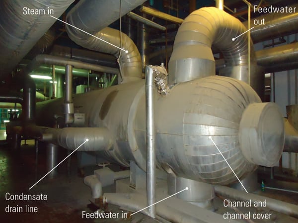
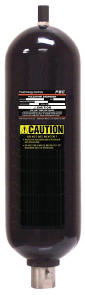
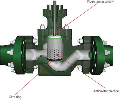
Power industry severe service applications can be difficult, but new advanced trim designs and external noise reduction devices have created higher-performing and more cost-effective alternatives.
Power industry applications practically define the phrase “severe service.” Elevated temperatures and pressures, cavitation, erosive solids, and high noise all conspire to push control valve technology to its very limits. Fortunately, technological advancements now provide a host of new solutions to these challenges.
This article reviews several severe service applications commonly found in the power industry, explaining the difficulties of each scenario and their effects on valve service life. Case studies are provided to illustrate how new solutions have been deployed to address these issues, dramatically increasing valve performance and reducing maintenance costs.
Severe Liquid Service Control Valves Address Cavitation and Erosion
Most severe service applications with liquids involve flashing, cavitation, and/or erosive solids entrained in the fluid. As liquids move through the confined space of a control valve trim, the cross-sectional flow area is reduced. This causes the liquid flow to speed up to maintain a constant volumetric flow and, per Bernoulli’s law, pressure falls. The flow reaches the vena contracta, where the flow velocity is at its highest, and the pressure and cross-sectional area are at their lowest. Once the liquid passes through the trim, the cross-sectional flow area increases, speed decreases, and the pressure recovers (Figure 1). The severity of the pressure drop and the amount of recovered pressure depends on valve design.
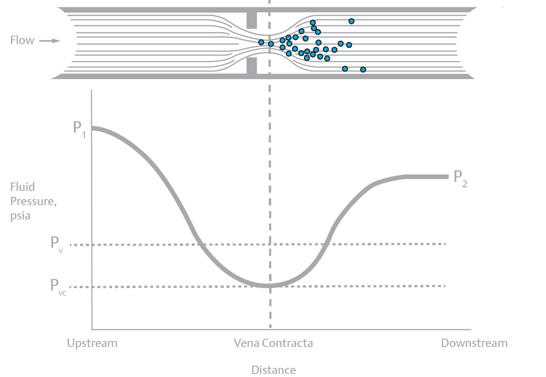
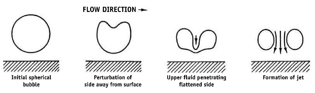
These pressure drops within the valve are not problematic unless the pressure falls below the vapor pressure of the liquid. Should this happen, the liquid begins to create vapor bubbles. Cavitation occurs when the pressure recovers back above the vapor pressure, causing the vapor bubbles to collapse back into a liquid. The imploding bubbles start as spheres but then develop a dimple, which continues to collapse as the bubble condenses back to liquid. As each bubble implodes, it generates high-speed, destructive microjets and localized shock waves that can erode the valve trim, body, and downstream piping. (Figure 2).
There are a number of ways to address cavitation. One method is to design trims that channel the destructive bubbles away from internal components, and/or incorporate hardened materials that will have an extended service life even under the cavitating conditions.
Another solution is to stage the total pressure drop into multiple smaller pressure drops, avoiding cavitation altogether. Older style multistage trims took equal drops across each stage, but this could still cause cavitation to occur in the final stages where the pressure was closest to the fluid vapor pressure. Newer designs employ unequal pressure staging, with higher pressure drops in early stages and small drops in the final stages, which can often avoid cavitation completely (Figure 3).
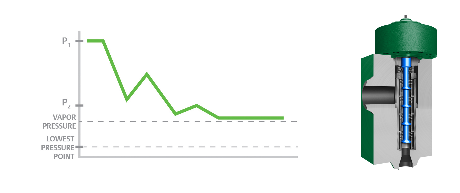
Anti-cavitation multistage trims may utilize many small holes or larger passages to stage the pressure drop. Trim style selection is based on valve style, pressure drop, liquid type, entrained particulate, and more.
Case Study: Reducing Cavitation, Plugging, and Maintenance Costs in a Power Plant Feedwater Valve
Very high pressure drops in liquid service are common in the power industry, particularly around large feedwater and condensate pumps, which have recirculation valves to maintain a minimum flow through the pump. In these cases, the recirculation valve is taking the full pressure drop of the pump, creating extreme turbulence, cavitation, and noise.
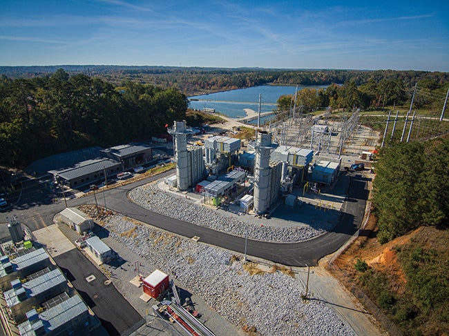
In one application (Figure 4), a control valve was taking more than a 2,300 psi drop when in operation, subjecting it to severe cavitation. A multistage, drilled-hole trim was installed for cavitation mitigation, but the small holes in the trim were constantly plugging with magnetite, constraining the valve capacity and restricting pump recycle flow. This prevented the power plant from operating at full capacity, reducing site production revenue by millions of dollars annually.
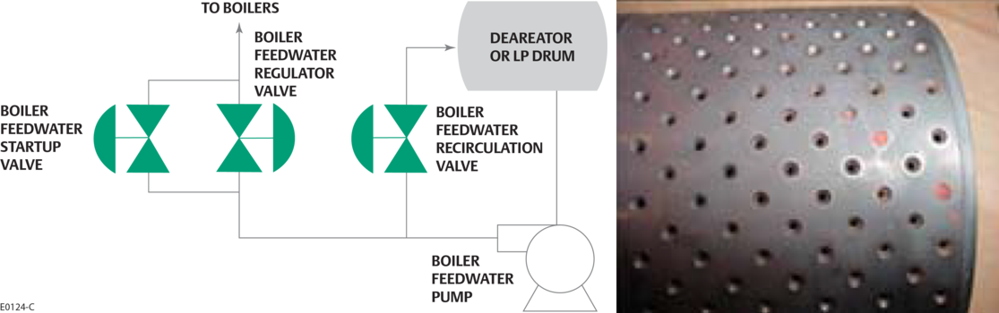
Cavitation and erosion were also damaging the valve seat, causing the valve to leak and require more frequent maintenance. This resulted in increased maintenance frequency. When leak rates got too high, downstream systems and piping would also become damaged. The increased system maintenance cost the power plant more than $120,000 in repairs annually. Additionally, this issue reduced the plant’s efficiency because the downstream steam drum did not receive optimal feedwater flow.
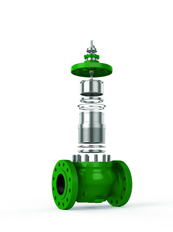
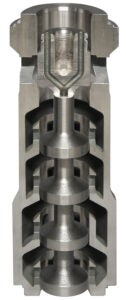
The solution was to upgrade the trim technology and material. The Fisher Dirty Service Trim control valve trim design was selected to better stage the pressure drop and allow the magnetite to pass through the valve (Figure 5). This legacy trim also got a modern upgrade via additive-manufacturing. By printing the trim, the design could be made more compact and with fewer parts, simplifying installation and maintenance. Also, the trim was printed completely in a high strength, wear-resistant alloy to enhance resistance to erosion and cavitation, while maximizing the trim’s service life.
Once installed, valve plugging, leakage, and erosion problems were eliminated, saving approximately $120,000 a year in maintenance and equipment costs, while increasing site production revenue by $7,000,000 a year.
Severe Vapor Service Control Valves Reduce Noise and Vibration
Severe service conditions in gas and vapor applications can result in extreme noise and vibration. The rapid expansion, deceleration, and change of flow direction through a valve body and trim contribute to noise and vibration. In many cases, the higher the pressure drop, the more noise generated in the valve. At extremely high sound levels, vibration can physically damage the valve and adjacent equipment, and put operators at risk for long-term hearing loss.
Two methods to reduce noise are path suppressants and source treatment. Path suppressants strive to minimize noise emanating from piping systems and valves using methods such as thicker-walled pipe, heavy insulation, and acoustic blankets. While path suppressants reduce operator exposure to the sound, the noise will still propagate downstream, so equipment damage can still occur.
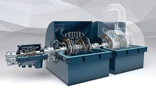
Source treatment reduces valve noise by separating large flows and shifting frequencies out of the audible range. In control valve trims, these source treatment methods take the form of small, specially designed slots or holes. These break up large noise-producing jets generated in the valve trim into smaller, quieter jets. While effective, these low-noise trims restrict the flow, so a larger size valve may be needed to achieve the required flow rate. Additive manufacturing has enabled cutting-edge designs that achieve much higher flow capacities for a given valve size, even as they dramatically improve noise reduction (Figure 6).
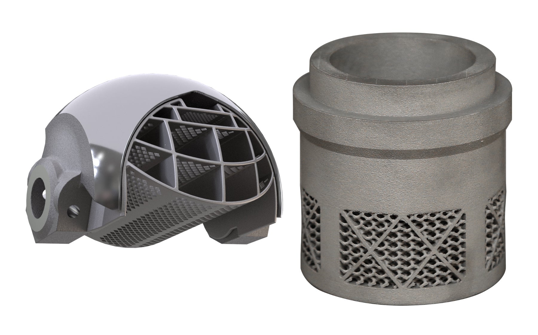
These designs allow more economical rotary valves to handle some high-noise applications that could only be handled by sliding-stem valves in the past. For applications with higher noise attenuation demands, new high-capacity sliding-stem valve trims allow smaller valves to be used, saving significant capital costs.
A new path-treatment approach has recently become available with the Fisher WhisperTube Modal Attenuator (Figure 7). This device uses a straight-through, cylindrical screen as the primary flow path. Surrounding the screen are acoustic cavities in which sound waves over a range of frequencies cancel themselves out through destructive interference. The result is broadband noise reduction of 10 dB(A) to 15 dB(A) with negligible pressure drop and no impact on process flow.
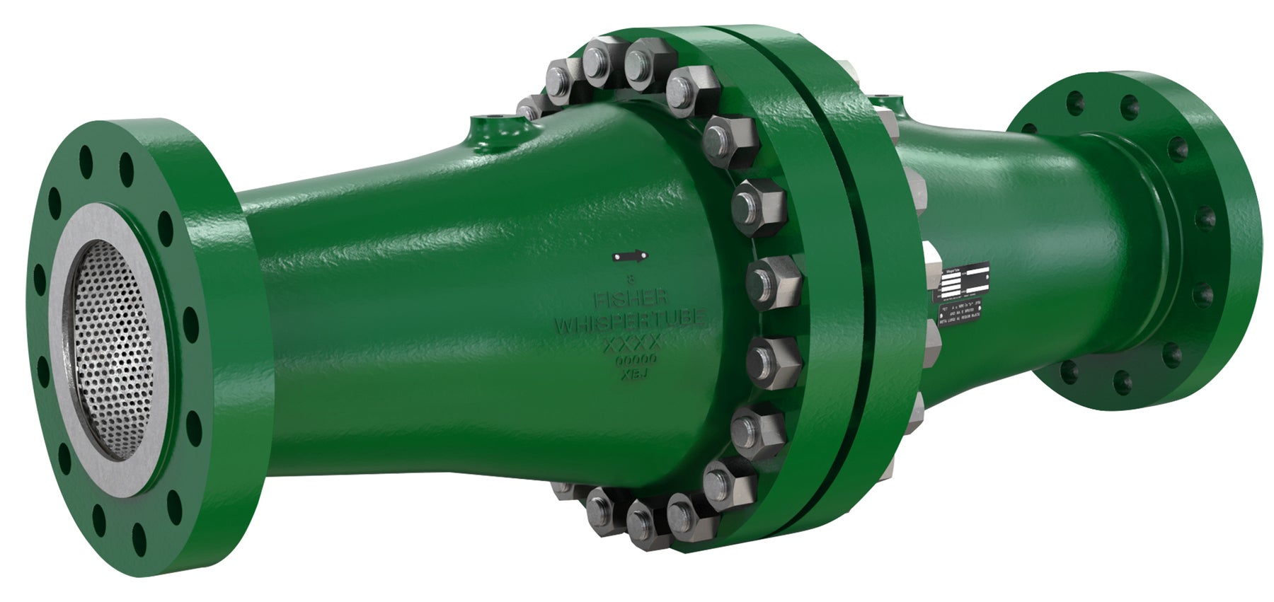
The device can be used alone, or in combination with other noise-reduction trims, to achieve the optimal balance of noise reduction and flow capacity.
Case Studies: Reducing Control Valve Noise in Power Plant Steam and Gas Applications
In one instance, a large power plant had two existing NPS 12 rotary valves with downstream diffusers installed on its low-pressure steam pegging system. The diffusers were installed to reduce noise, but over time the sound levels increased while valve performance deteriorated due to wear and tear. Plant personnel initially considered replacing both the valves and diffusers, but the price point was very high, and noise reduction could not be guaranteed. The site pursued an alternative solution using NPS 12 Fisher Vee-Ball V150 with Whisper NXV trim. The Vee-Ball with Whisper NXV trim easily achieved the plant’s noise reduction goals, provided higher flow capacity, and dramatically reduced the overall project cost.
In another instance, a newly built power plant was to be fed by a 10-inch gas line incorporating redundant worker/monitor pairs of pressure-reducing valves to control gas pressure to the site. Inlet pressures ranged from 450 psig to 600 psig and gas flows varied from less than 30 million standard cubic feet per day (MMSCFD) to more than 50 MMSCFD. The valves were to be installed close to the plant, and noise levels were predicted to approach 100 dB(A), potentially subjecting the staff to dangerous sound levels.
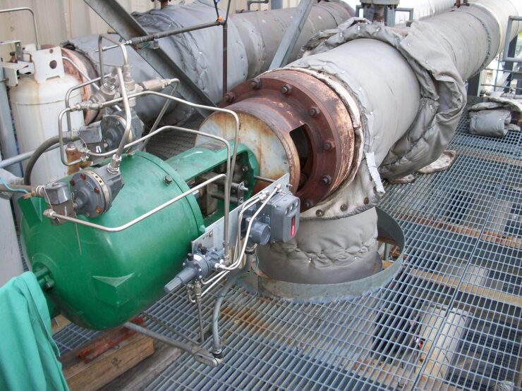
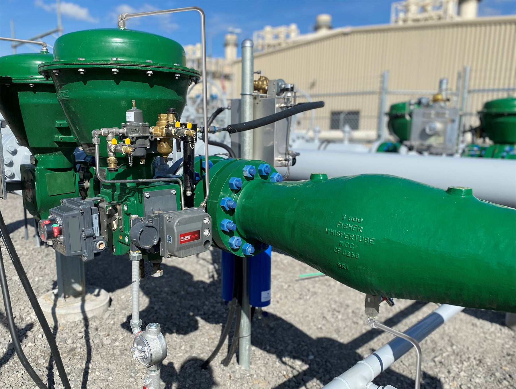
After evaluating various options, the site chose to combine Fisher Vee-Ball V200 valves with rotary attenuators, and WhisperTube devices downstream (Figure 8). Once installed, this arrangement reliably reduced sound pressure levels from the predicted 100 dB(A) to field measured 83 dB(A) across the range of flows and inlet pressures.
When to Consider Severe Service Control Valve Upgrades for Power Plants
Innovations in control valve technology have created a whole new set of solutions to address severe service control valve applications in power plants. If your site is struggling with a particularly difficult application, or if it is facing consistent valve failures that are consuming maintenance budgets and affecting production, it may be time to consult your automation partner and investigate possible solutions.
New valve designs have larger passages to accommodate embedded solids in liquids, and multistage trim designs can all but eliminate cavitation, even in extreme pressure drop applications. High noise vapor applications can be addressed with a combination of high-capacity, efficient low-noise trims and modal attenuators, creating very-high-performance, high-flow-capacity solutions.
Severe service applications may seem like insurmountable problems, but a little research and some aid from a knowledgeable automation partner can often reveal reduced cost alternative valve designs that address the problem, while providing higher performance than previously possible.
—Shelby Daniels is a product marketing manager; Justin Goodwin serves as a business development leader, specializing in custom control valve solutions; and Chris Vergos is a severe service sales engineer, all with Emerson’s flow controls business.