Boiler feedwater valves operate under severe service conditions and are subject to premature failure from seat leakage, cavitation, particulates, and frequent cycling. However, once the type and root cause of damage is properly understood, installing the appropriate trim can solve most problems.
In competitive power markets, combined cycle facilities are experiencing more operating cycles than owners initially planned for at the design stage. It’s not uncommon for a combined cycle plant to experience more than 250 starts per year these days.
While the ability to cycle a large combined cycle plant is ideal for fleet flexibility, frequent startups and shutdowns strain many critical components and limit their lifetimes. Witness the relatively common boiler tube failures caused by flow-accelerated corrosion (FAC) and the premature failure of steam turbine bypass valves. Similar problems with feedwater valves have been experienced at several combined cycle plants with different types of steam turbines and heat recovery steam generators (HRSGs).
Such problems can bring a plant down for extended periods, often without warning. Given that there are up to eight critical boiler feedwater valves per HRSG, maintenance or replacement of these valves can be very expensive. The cost of feedwater valves for a two-on-one combined cycle plant can run more than $160,000.
While many problems can be traced to frequent cycling, there are other reasons for feedwater valve damage. The application is an inherently severe service; a combined-cycle plant using F-class combustion turbines will employ feedwater pressures as high as 3,000 psig, and some repowering projects have pressures climbing above 4,000 psig. Valves operating in such high feedwater pressures encounter a potential for cavitation damage.
Another common feedwater valve issue is excessive leakage, which is typically revealed by an increase in drum water level. With leakage comes damage to the internal throttling and seating surfaces of the valve. Once it is determined which valves leak, they must be opened for inspection to determine the root cause. It is important to understand the type of damage and its cause before the proper replacement or fix can be applied.
One problem occurs when feedwater valves are not specified for tight shutoff. ANSI (American National Standards Institute) and FCI (Flow Control Institute) have established criteria to denote leakage classes for control valves. Table 1 shows the corresponding leakage of 3-inch and 4-inch feedwater valves. Class V shutoff is recommended for feedwater valves exposed to cavitation conditions.
 |
|
Table 1. Acceptable leakage rates for various American National Standards Institute (ANSI) and Fluid Controls Institute (FCI) valve classes are shown here in gallons per minute (gpm). Source: Emerson |
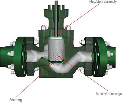
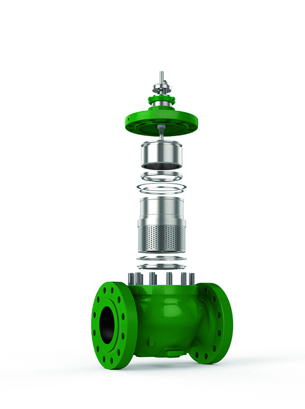
Looking at the table, it is easy to understand what can happen to the drum-level valves if they are not Class V. Flow that leaks past the seating surface will cavitate, damaging the seating surfaces of the plug and seat ring, exposing the valve to further damage. It is very likely that feedwater valves in existing service may have been installed with a Class IV shutoff rating or less. To upgrade a valve without Class V (CLV) shutoff, a simple trim change (Figure 1) will solve the issue.
 |
|
1. Upgrading a boiler feedwater valve’s trim can stop leaks. Courtesy: Emerson |
Sometimes, a feedwater valve may have CLV shutoff listed on the customer specification sheet or serial card, but it might not actually be achieving this shutoff. The lack of shutoff may simply be from a lack of appropriate seat load force from the actuator. An easy adjustment to ensure that the seat load is being provided is to set up the actuation package to provide 800 pounds of force per lineal inch. Moreover, a change in the actuator and some additional accessories may be necessary to attain the required seat load for adequate shutoff.
When a new power plant is initially engineered and designed, pump characteristics are not always available during the valve selection phase. As a result, the installed valves may not have been properly sized for startup conditions or other limitations imposed by the pump manufacturer.
Conservative design practices often result in an oversized valve. This means that the valve must operate at lower lifts (30% to 40% open) than intended during normal operating conditions, thereby exposing seating surfaces to premature erosion during startup. Retrofit trim packages that alter the performance characteristic of the valve can be supplied.
Sometimes problems are introduced by the way a valve is operated. All control valves have a minimum operating point. If a valve is opened only a minute amount off the seating surface, the plug and seating surfaces can experience erosion.
Valves supplied with anti-cavitation trim eliminate the formation of damaging cavitation by staging the pressure drop through the valve trim. For this trim to be effective, a certain number of flow passages must be exposed. If they are not, all the pressure drop will occur across the last stage of the trim and the seating surfaces, creating high local velocities that will erode the plug and seat ring.
To protect against this, valves should not be throttled below the manufacturer’s minimum travel recommendation. A rule of thumb is not to operate valves below 10% open. This ensures that the pressure drop occurs in the valve trim, not across the seating surface. An interlock in the control system logic to prevent operation below a certain input signal, or a low-travel cutoff programmed in a digital valve controller, help to avoid this.
There are multiple leak paths within a control valve in addition to the plug and seat ring. Standard seal ring designs may work sufficiently to maintain valve shutoff. However, as increases in plant cycling occur, and process pressures and temperatures rise, older sealing types may prematurely wear out or simply be unable to withstand the process conditions.
Sealing technologies have advanced substantially in recent years. For moderate process temperatures below 600F, seals have been improved to last longer and shutoff better. A newer sealing technology can often be retrofitted into the existing valve trim design. Metal seals are available for process temperatures above 600F. Upgrading the seal material is also a simple change of a few trim components.
Seal issues in high-temperature situations can also be addressed through changing the trim design. Moving to an unbalanced trim design removes the need for seals and therefore removes the secondary leak paths altogether. If moving from a balanced to an unbalanced design, the actuator capabilities should be reviewed in addition to new trim.
The aforementioned FAC and other contaminants cause particulates to build up in the system. These entrained particulates create accelerated wear to the plug and seat ring. Fine particulate matter is not captured by the strainers typically installed in many new plants, and it essentially “grit blasts” critical surfaces. Erosion of the valve plug can lead to leakage, additional valve damage, and eventually the plug wedging into the seat ring.
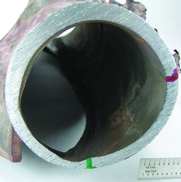
Figure 2 shows a valve plug that has “gear-tooth” erosion at the bottom of the plug. This is commonly found in boiler feedwater valves that have been exposed to particulates. Because the seating surface had been damaged the valve now has decreased shutoff capability and the additional leakage through the valve will only exacerbate the problem.
 |
|
2. Particulates caused “gear-tooth” erosion to this valve plug. Courtesy: Emerson |
One solution is to install trim with a protected inside seat design. This design moves the seating surfaces out of the direct flow path and to the center of the plug, prolonging trim life. Protected inside seat designs can be installed by a simple change of plug/stem and seat ring.
Entrained particulates can damage other valve trim components. Particulate matter can become lodged between the plug and cage causing galling and scoring of those surfaces as well as reduced valve capacity. Valves equipped with anti-cavitation trim that become plugged may no longer stage the pressure drop effectively. This leads to cavitation damage on many trim components and, in severe cases, valve bodies.
Anti-cavitation trims that have been plugged can be retrofitted with trim that has larger flow paths and a protected seat design while offering cavitation protection. The larger flow paths allow entrained particulate to pass through the valve while staging the pressure drop to avoid cavitation.
The protected seat design removes the shutoff areas away from any areas where a pressure drop may be taken. By ensuring that a pressure drop does not occur across the seating surface, the high-velocity grit-blasting effect from the entrained particulate cannot occur, and the trim is protected against premature erosion.
Much of the entrained particulate in boiler feedwater can be linked to inadequate pipe blowdowns during plant startup and commissioning. Once in operation, additional entrained particulates formed from FAC will be expelled through continuous and intermittent blowdown operations, but it can take several years to complete the process.
Inadequate pipe blows have caused the failure of many valves, not just feedwater valves. But feedwater valves are particularly susceptible to particulate damage because debris can become lodged in the flow passages and reduce capacity. In valves with flow passages large enough to remain open, this can cause jerky motion of the valves, a phenomenon that hampers control. The worst case is that it renders the valve completely useless if the plug becomes stuck.
Ensure that proper piping blows are conducted. Prior to a pipe blow, it is necessary to remove the normal operating trim from the valve and install sacrificial trim. Emerson offers such Fisher valve trim along with support from Lifecycle Services to handle operational trim removal and replacement. This will protect the finished surfaces from damage while also acting to either catch the particulates passing through the valve or to let them pass through without obstruction. Protecting these critical valves in such a way reduces lost production due to downtime at startup. ■
—Shelby Richardson is a sales engineer with Emerson in Marshalltown, Iowa, supporting flow controls products.