Turbine bypass valves are one of the most difficult applications in a power plant. Keeping these valves operating efficiently and avoiding unexpected failures is critical for plant operation.
When engineers are asked to list the most difficult control valve applications, turbine bypass valves are invariably mentioned. Frequent thermal cycles, high pressure drops, and the need for tight shutoff push these valves to the limit. Unfortunately, many plants tend to ignore these valves until they fail, creating unplanned outages, lost production, and high costs for reactive maintenance. This article provides suggested methods of inspection to anticipate and mitigate issues beforehand, and it offers upgrade alternatives should a valve need to be repaired or replaced.
Strictly Severe Service
Severe service control valves are used in the most difficult installations within process plants. These installations commonly include cavitating, erosive, corrosive, noisy, high pressure, high temperature, high pressure drop, or high velocity media. Turbine bypass valves are exposed to many of these process conditions; yet, they must respond flawlessly and remain leak free when closed.
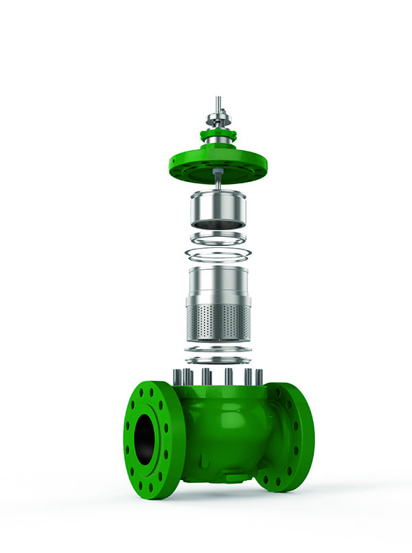
As their name suggests, turbine bypass valves are used to bypass steam turbines during plant startup and shutdown, as well as when a turbine trips off-line (Figure 1). In normal operation the valves are completely closed, forcing all the steam through a turbine. During startup, bypass valves divert steam away from the turbine until the properties and conditions of the steam are appropriate for sending it to the turbine. This process happens in reverse at shutdown. Using bypass valves at startup and shutdown helps to protect the turbine by diverting potentially wet steam, and by ensuring only appropriate steam conditions and flows make their way to the turbine itself.
 |
|
1. Depending on the power plant design, several turbine bypass valves may be employed to instantly shunt steam around a turbine should it trip offline. Courtesy: Emerson |
Should a turbine trip, the steam must continue flowing to avoid equipment damage due to overpressure and high temperature, so the turbine bypass valve immediately opens to maintain flow through the system.

In This Issue
Full issueAs it operates, a turbine uses steam to perform work, reducing outlet steam temperature and pressure. When a turbine bypass valve opens, it will drop the pressure, but the exit steam will remain quite superheated, potentially destroying downstream equipment. To avoid that situation, turbine bypass valves either incorporate a water injection system in the valve body, or employ a separate water injection desuperheater just downstream, in either case to lower the exit steam temperature.
As a result, turbine bypass valves face a perfect storm of severe service conditions. While the plant is in operation, these valves must remain tightly closed to avoid wasting energy. When a turbine trip occurs, the bypass valves must respond immediately, exposing them to rapid temperature changes and requiring them to pass very high flows at high pressure drops, creating high noise and potentially extreme vibration.
Getting Ahead of the Game
Given the punishing service, the reality is that virtually every turbine bypass valve will ultimately fail in some way. Unfortunately, many of these valves are installed in difficult-to-access locations, are typically welded in place, and tend to be heavily insulated. As a result, they are often ignored until problems start to surface. Steam leakage through the valve is usually the first symptom noticed, but much more significant and potentially dangerous damage can occur.
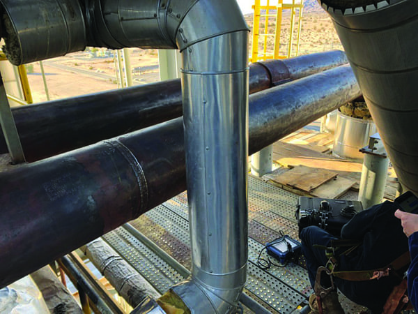
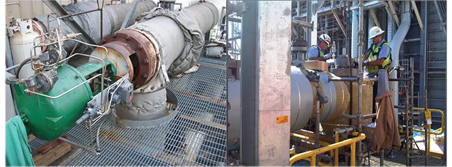
The extreme pressure drops invariably generate high noise and high vibration. Over time these vibrations, coupled with frequent temperature changes, fatigue the metal in the valve, water connections, and the piping itself (Figure 2). Such metal fatigue can result in catastrophic failure under pressure.
 |
|
2. Over time, the high vibrations and thermal shock experienced by turbine bypass valves will fatigue the metal and create cracks in both the valve itself and the surrounding piping. Courtesy: Emerson |
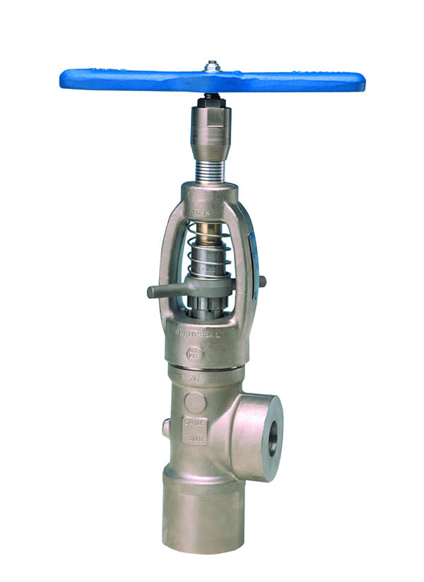
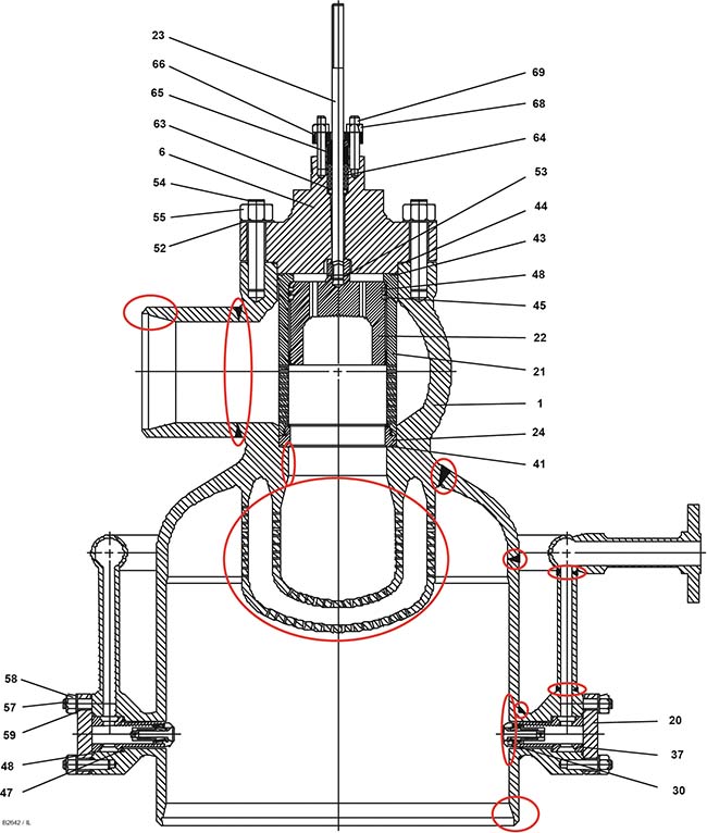
To avoid this problem, every turbine bypass valve and its associated piping should be routinely inspected. Some type of non-destructive examination should be periodically employed to detect metal fatigue problems that may be developing but are not yet visually apparent. If a plant lacks the knowledge or equipment to perform these inspections, the valve vendor or authorized representative may be utilized to perform turbine bypass health check services (Figure 3).
 |
|
3. A routine turbine bypass valve health check and full inspection is strongly advised. Metal fatigue can develop in various welds located on the valve itself, and in the inlet, outlet, and water supply piping (circled areas). Courtesy: Emerson |
Fabrication welds on the body and water manifold, customer connection welds, diffuser welds, and surrounding piping can be inspected to identify any developing problems before the equipment is compromised. Water injection nozzles and desuperheaters must be appropriately inspected and maintained to avoid problems related to quenching and cracking.
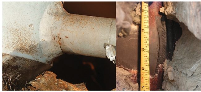
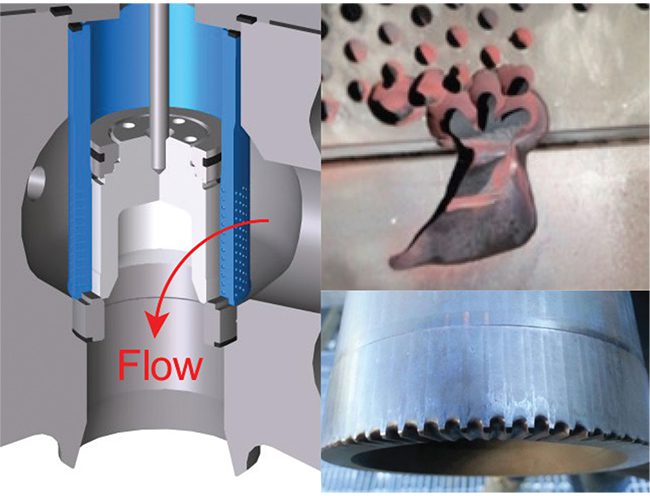
There are also threats to trim components, such as seat surface erosion. One common expression of such erosion, specifically on the plug, is often referred to as “gear toothing.” This occurs more commonly in flow down valves, where the steam accelerates through the cage holes and then strikes the trim/seat area directly, causing excessive wear and reducing service life. Over time, this high-velocity steam, which can contain water during startup conditions and magnetite during any condition, will erode and damage the valve seat and trim (Figure 4).
 |
|
4. Flow down valve body designs are prone to trim damage as the wet, erosive steam passes through the cage and impacts the seat. Courtesy: Emerson |
Common maintenance items like soft goods and spray nozzles can usually be replaced relatively easily and at minimal cost. Trim components that need to be replaced due to heavy wear, such as gear toothing, can be quite costly, especially if their delivery needs to be expedited. The worst-case scenario for a turbine bypass valve is metal fatigue developing in the valve body or diffuser, with extreme repair procedures, or even a complete valve replacement, required.
Upgrade Opportunities
Many of the turbine bypass valves currently in service were installed during the heyday of combined cycle plant construction from 1998 to 2004. Most of those valves and piping systems are showing their age and often have significant signs of metal fatigue. Others have plenty of life left in them but could benefit from upgrades in technology. Technology and practices have improved, and upgrading to the latest sealing technology could inject new life into the valve.
Another example of a technology upgrade is when there have been repeated failures with a welded diffuser. In this instance, a removable two-in-one seat diffuser will reduce required maintenance.
If a turbine bypass valve must be replaced, plant personnel are strongly encouraged to look beyond a direct replacement and evaluate potential improvements. A particularly important item to consider when looking at replacement and improvement opportunities is valve orientation.
Downward Flowing Valves with Horizontal Actuators. Historically, most turbine bypass valves employed a flow down trim design paired with a horizontal actuator (Figure 5, left). This arrangement is ideal for locations with low overhead clearance, and it places the actuator closer to the deck or ground for easy access, but it creates a number of long-term operational problems. Gravity tends to result in increased and uneven wear on trim components, and the side-mounted actuator is prone to response problems.
 |
|
5. Downward flowing valves with horizontal actuators (left) were the main option a few decades ago for turbine bypass valves. New flow up valve designs (right) may be installed without piping modifications in most instances, providing extended service life and improved performance. Courtesy: Emerson |
Downward Flowing Valves with Vertical Actuators. A superior option for flow down is vertical mounting of the actuator. This arrangement results in reduced and more even wear, longer runs between maintenance outages, and improved actuator response. The challenge with this orientation is that replacement opportunities are typically for horizontally mounted actuators, and the two designs are not readily interchangeable without significant piping modifications.
Upward Flowing Turbine Bypass Valves. When sufficient overhead space is available with existing horizontal actuator flow down designs, a flow up design can easily meet the existing face-to-face requirements of the old valve, while reducing some of the wear common to flow down designs with a horizontal actuator, such as gear toothing. Because the trim just switches from flow down to flow up, this change can be made without modifications to existing piping.
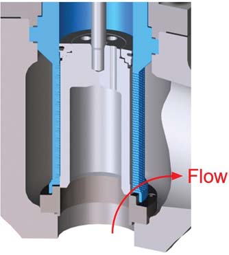
Flow up valves (Figure 5, right) significantly extend seat and trim service life because the steam is moving relatively slowly as it passes over the plug and seat (Figure 6). As the steam moves through the small holes of the cage, it accelerates significantly, but that energy dissipates into the large body cavity of the valve instead of striking the seating surface.
 |
|
6. Downward flowing valves subject the seat to erosive high-velocity steam. Upward flowing steam velocities are much lower because they pass over the seat and accelerate later as the steam moves through the small trim holes, greatly extending trim service life. Courtesy: Emerson |
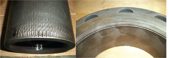
Notice how the flow up trim (Figure 7) is certainly showing erosion, but when compared to the flow down trim shown above (Figure 4 right), the seating surface on the seat ring and plug remain relatively undamaged, allowing the valve to shut off completely, the required mode in normal operation.
 |
|
7. These pictures of flow up trim clearly show the erosive impact of high-velocity steam, but unlike the flow down trim damage shown previously, this valve has no damage to the seating surface and can still shut off tightly. Courtesy: Emerson |
The flow up valve style design still provides the same control responsiveness and flow capacity, but the new flow arrangement dramatically extends the operating life of the seals, seat, and valve internals.
Consult an Expert
Turbine bypass valves are highly specialized pieces of engineered equipment that must be carefully specified, installed, and maintained. It is therefore wise to be proactive by reaching out to trusted experts prior to purchase as they can assist with valve sizing and specifications based on specific operating conditions.
For existing installations where unplanned turbine bypass valve failures are bedeviling your facility, or if it has been some time since the plant turbine bypass valves have been fully inspected, it would be wise to consult your turbine bypass valve vendor for help and support.
Many of these vendors offer full inspection and health check services to identify areas where metal fatigue and stress cracking are developing. Ideally the valve can be repaired, but if a valve replacement is warranted, the vendor can also provide guidance in evaluating bypass valve design styles and choosing the best option for the specific application.
—Chris Roling is a product engineer in the Steam Conditioning Group at Emerson.