Sudden bumps and shocks are great fun when you are off-roading or are riding on a rollercoaster. But when you are operating a piece of equipment, you want it to be running as smoothly as a Cadillac rolling down the interstate. Sudden changes in pressure produce vibration, cavitation, and water hammer and generally lower the lifespan and reliability of fluid systems.
The basic problem with pressurized fluid systems is that liquids are not compressible. There will always be changes in pressure and flow brought about by such things as the opening and closing of valves, restrictions in piping, or the action of a reciprocating or rotary pump. Because those pressure changes can’t be balanced by a change in the volume of the fluid, either a portion of the fluid converts to a gas or there is column separation, producing cavitation, and/or the energy hammers against the other components.
The solution is to introduce a compressible element, such as a gas, into the system, which will accommodate the changes in flow and pressure. The following is a rundown of some of the options for maintaining an even pressure and increasing equipment reliability.
Pulsation Dampeners
In most liquid-handling systems, the primary source of pulsation is the pump. This applies to both hydraulic motion systems and chemical injection pumps. With any type of positive displacement pump—whether it uses a diaphragm, gear, piston, or vane—the pump breaks down the inlet flow into a series of discrete volumes. The pump then applies energy to each of these discrete volumes, raising its pressure and then releasing it into the general high-pressure flow.
While the average pressure and flow rate of the fluid remain relatively constant, it is subjected to wide fluctuations, particularly in the area immediately following the pump output. The pump operates by taking a finite amount of fluid into its chamber and then rapidly compressing it. This action produces a sinusoidal pattern of fluid pressure and speed, fluctuating around the average pressure and speed of the system.
As the high-speed, high-pressure fluid exits the discharge port on the pump, it creates a compression wave. That wave travels through the fluid at the speed of sound until it reaches a bend or restriction in the pipe. At that point, the joint or restriction absorbs some of the compression wave’s energy, while the rest is reflected back against the flow coming from the pump. This back-and-forth hammering from the compression wave lowers the life of the pump and the components in the pipeline.
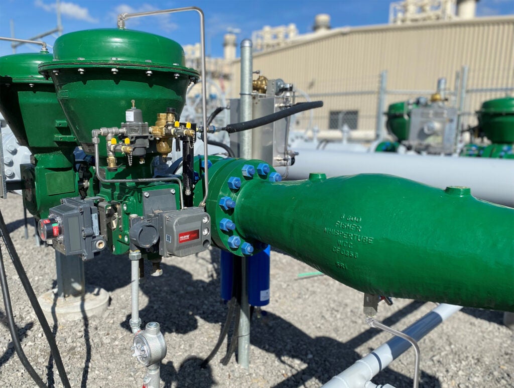
Pulsation dampeners are devices attached to the pump output that moderate the pump’s pressure and volume fluctuations. They can be attached on a tee off the outlet line, or they can sit inline. Numerous designs are available, but the basic elements consist of a sphere containing a diaphragm or a cylinder containing a bladder (Figure 5). With the first design, the diaphragm is held in place by the two halves of the sphere. The diaphragm splits the interior of the sphere into two halves—one contains nitrogen and the other the fluid being pumped. A charging valve and a pressure gauge are connected on the gas side of the sphere, while the fluid side connects to the plumbing. The cylindrical design is similar in operation, but a bladder is attached to the charging valve. The gas is contained within the bladder while the fluid flows between the cylinder and the bladder.
 |
| 5. Smooth operator. A 5-gallon accumulator is used to dampen the pressure and volume fluctuations of the discharge from a pump. Courtesy: Fluid Energy Controls |
In both cases, the gas side of the dampener is precharged to about 80% of the minimum allowable system pressure, so that there will always be some liquid within the dampener. When the fluid is pressurized quickly, with the nitrogen being more compressible than the hydraulic fluid, most of the fluid above the average system flow goes into the pulsation dampener rather than creating a compression wave. Similarly, during the low-pressure portion of the piston stroke, the gas expands to force the fluid back out of the dampener into the system, maintaining the mean flow and pressure. The elasticity of the rubber and the compressibility of the gas work together to eliminate more than 95% of the variations in flow and pressure, hence prolonging equipment life.
Surge Suppressors
First, understand that surge is very different from pulsation. The latter is the regular acceleration and deceleration of the fluid, typically caused by the cyclical actions of a reciprocating pump. Although pulsation can be solved by installing a properly sized pulsation dampener at the pump outlet, surge is less predictable and can cause severe damage to pipes, valves, fittings, and pumps.
Fluid systems never operate at a constant pressure. Pumps going on- and off-line and changes in temperature, demand, and tank levels alter system flow rate and pressure at any given time. A mild pressure change, also called a surge, results in fluid pressure oscillations within the system and can damage the pipes, valves, and fittings. This oscillation of the pressure is called water hammer.
The more severe water hammer, on the other hand, comes about when there is a sudden change at either the inlet or outlet of a system. Pumps suddenly going on- or off-line, or valves rapidly closing are the most common causes. Fluids at liquid state are largely noncompressible. This is what allows you to apply pressure at one end of a pipeline and attain pressure throughout the system.
When an outlet valve suddenly closes, the energy contained in the water flow compresses the water nearest the valve. Like a spring, this energy then reverses flow, sending a shockwave at the speed of sound back upstream until it hits an obstruction, such as a joint, another closed valve, or the impeller in the pump. Most of the energy from that shockwave then bounces off that obstruction and returns to hammer the valve again. The wave travels back and forth between the obstruction and the valve until friction finally dissipates the energy.
Another problem can occur when a pump suddenly shuts down, perhaps due to a power outage. When this happens, the fluid column may experience a sudden drop in pressure, causing a separation in the fluid column, with some of the fluid becoming vapor. When the pressure increases once again above the vapor pressure point, the collapse of the vapor pocket sends a shockwave through the system.
Surge suppressors are similar in design to pulsation dampeners, but they are built to address much larger pressure and volume fluctuations. The bladder is precharged to a level lower than the minimum allowable system pressure so that there will always be some liquid within the surge suppressor. When there is a pressure surge, most of the fluid under higher-than-average pressure in the system flows into the surge suppressor and, consequently, dissipates the compression wave. When there is a sudden drop in pressure, the gas expands to force the fluid back out of the surge suppressor, so there is no danger of causing a column separation.
Other than size, one key difference between a pulsation dampener and a surge suppressor is where they are installed. The pulsation dampener should be placed as close to the pump outlet as possible. Surge suppressors, on the other hand, will be needed at various points throughout the system. They can be installed at the pump outlet to prevent damage if the pump loses power. Others can be installed at critical points in the piping network where pressure surges may happen, such as upstream from a quickly closing valve.
Bladder or Diaphragm Accumulators
Though surge suppressors and pulsation dampeners are designed to minimize the damage caused by an increase in pressure, accumulators are designed to prevent a pressure drop. A common application is called a LOSA (lube oil system accumulator), which provides a temporary source of oil in the event of a flow disruption. Hydraulic accumulators are energy storage devices that smooth the pulsation of oil pumps and provide short-term oil pressure when there is a power outage or during switchover between oil pumps. Accumulators also help maintain a constant oil pressure during temporary changes of demand (Figure 6).
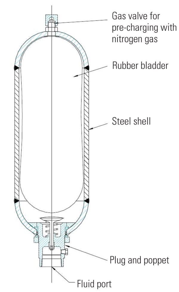 |
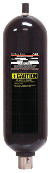
| 6. Cheap insurance. A bladder accumulator with a plug and poppet construction will provide a temporary source of oil in the event of a flow disruption. Courtesy: Fluid Energy Controls |
An accumulator is essentially a pressure vessel that stores oil and contains a mechanical means of maintaining pressure when the pump shuts down, thus cushioning fluctuations in oil pressure.
Accumulators differ in the type of mechanical means used, such as spring, gravity, and gas load. Gas-loaded accumulators use compressed gas to provide pressure and are one of two types: separator and nonseparator accumulators. Nonseparator accumulators do not have any barrier between the gas and the liquid. This is the simplest design and can store the greatest amount of oil. However, because there is no barrier separating the gas from the oil, the gas may become absorbed by the fluid, particularly at high pressures. Then, as the pressure drops, the absorbed gas forms bubbles in the oil, causing sponginess in the system that may damage the pump through cavitation.
Bladder-type accumulators consist of a metal cylinder containing a pressurized bladder. They are designed in accordance with American Petroleum Institute Standard 614/ISO 10438, which covers lubrication systems, and ASME Pressure Vessel and Boiler Code, Section VIII, Division 1. In accordance with the standards, these accumulator vessels are made of 300 series stainless steel and can withstand maximum pressures of about 1,500 psi.
Because of its high flexibility and low weight, the bladder has a rapid response time, allowing the accumulator to quickly compensate for pressure drops in the system and prevent damage to bearings and other components.
Diaphragm accumulators serve a similar function, and like the diaphragm pulsation dampeners, the accumulator vessel is also divided into two halves by a diaphragm. The basic construction of a diaphragm accumulator is similar to the diaphragm pulsation dampener.
Suction Stabilizers
Suction stabilizers perform a similar function to that of surge suppressors and pulsation dampeners, but they protect against a pressure drop on the inlet of pumps. Rather than absorbing excess liquid, they supply it when there is a pressure drop, such as during pump start-up. This lowers the risk of cavitation, head loss, and pulsation that can otherwise occur on the inlet of the pump and may damage the pump. It also prevents the low-pressure transients and spillback that injects frothing into the suction pipe, destabilizing the flow.
—Contributed by Joe Cheema, senior project engineer for accumulator manufacturer Fluid Energy Controls Inc. in Los Angeles, California.