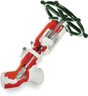
When high-temperature boiler feedwater passes through a control valve, the pressure drop can exceed several thousand pounds per square inch, placing extreme stress on the valve body and internal parts. If those parts are not engineered and manufactured to the highest industry standards, there is a very real possibility of the severe conditions damaging or destroying the valve. This risk is mitigated only if the entire assembly meets the original quality or original equipment manufacturer (OEM) specifications.
Buying the least expensive replacement parts might seem like a frugal move in difficult economic times, but potential users should understand the associated risks if they use low-quality parts. Unfortunately, end users generally have no way of determining if the parts are manufactured to OEM standards. Because the long-term cost of using inferior replacement parts may far outweigh the immediate savings, you should get satisfactory answers to a number of key questions before you buy:
-
Is the source reliable?
-
Do the parts measure up dimensionally?
-
Do the parts have the correct hardness?
-
Does the valve function as originally engineered?
Those are questions we were asked to answer in our laboratory recently after one of Emerson Process Management’s local business partners submitted a valve trim set for inspection and testing. This trim set had been sold to a major power company by a supplier of replicated replacement parts.
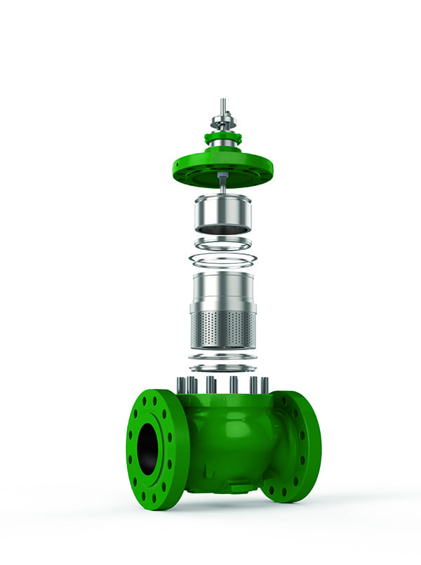
Trim sets can be designed to enable a valve to perform and survive under harsh conditions, including cavitation, flashing, and particulate matter in the flow stream. The first two conditions can be attributed to the large pressure change across the valve and can be controlled by a well-designed trim package. The trim set we were asked to evaluate, which was intended as a replacement for an original Fisher product, consisted of three parts: a plug/stem assembly, seat ring, and cage (Figure 6).
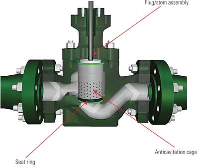
6. Similar but different. Fisher evaluated the trim set provided by a company that replicates OEM hardware. A trim set consists of three parts: a plug/stem assembly, seat ring, and cage. The replacement parts appeared to be identical to the eye but performed quite differently in laboratory testing. Source: Fisher Division, Emerson Process Management
The seat ring and plug/stem assembly were actually OEM parts that had been reworked for reuse and appeared to be in good condition. A careful examination found the critical dimensions to be within tolerance. Using these parts should not be a cause for concern.
The same could not be said for the all-important cage, which was manufactured by the replicator in an attempt to copy the Fisher Cavitrol III cage with three stages. Three-stage Cavitrol III trims can eliminate cavitation noise and damage in a valve when properly applied. This trim is normally used where pressure drop is up to 149 bar (~2,100 psig) for two-stage and 207 bar (~3,000 psig) for three-stage trim. Liquid passes through cage orifices in each stage, undergoing a portion of the total required pressure drop. This partial pressure drop in each stage of a properly sized and carefully manufactured valve trim is intended to prevent the liquid pressure from falling to, or below, its vapor pressure, eliminating the formation of vapor bubbles.
As it turned out, the cage sent for testing had a number of significant flaws and was potentially dangerous. These flaws could lead to performance and operational issues, which could lead to unexpected outages and lost revenue.
Dimensional flaws. It was obvious on first inspection of the cage that the replicator did not make one hole on the outer diameter even though it exists on the inner diameter (ID). Hole sizing on the ID was found to be incorrect when checked against the original drawing for that part. The replicator’s cage had only ~40% of the holes correct.
Holes in the cage also did not follow the correct geometry as per the drawing. In some cases, the largest holes were too close together, leaving almost no material between them. Nor did the holes follow the drawing, indicating a very careless transition between hole sizes. The other dimensions were within tolerance.
According to valve engineers with years of experience designing trim sets for high-pressure valves, these manufacturing inconsistencies could lower the flow capacity of the valve. In addition, cavitation protection may be compromised.
Hardness. There are sound engineering reasons for specifying a certain level of cage hardness to withstand erosion caused by friction within a valve body and by particulate matter in the process fluid. Also, closely fitting trim parts must have the same coefficient of thermal expansion so they can expand and contract at similar rates. If the materials are not compatible, the parts could seize up when heated to temperatures as high as 300F to 400F, or it may be impossible to achieve complete valve shutoff.
The material of the cage tested was found to match the specification, but the hardness varied greatly around the diameter of the cage, from 12 HRC to 35 HRC. Any hardness level below 31 HRC is unacceptable for service where cavitation is a possibility.
The most common explanation for variations in material hardness is that too many parts were placed in the heat-treat oven at the same time and some parts may have been touching each other. However, the wide variations in this particular cage led us to believe that it was never heat treated. Specifications for the heat treatment require particular temperatures and times at which parts are to be held. There is very little room for deviation from the designated method when trying to achieve a specific hardness. If this part had been given the proper treatment, there would have been little to no variation in material hardness. Of course, skipping heat treatment altogether enabled the parts replicator to keep prices low — with quality to match.
Choking and flashing cavitation are conditions of flowing liquids that correspond to the limits of pressure recovery. When pressures inside or downstream of the valve drop to the vapor pressure, cavitation occurs. This is a liquid phenomenon based on the formation and subsequent collapse of vapor bubbles in the fluid passing through a valve. Cavitation can produce noise, vibration, and erosion or damage to the valve and downstream piping.
Flow through the valve will not increase with a further decrease in downstream pressure or increase in upstream pressure, thus it is "choked." Data from testing of the replicator trim set in Emerson’s R.A. Engel Flow Lab (see table) show choking conditions when the valve is open about 50% or more. A valve that is experiencing choking cavitation is operating at the most severe level of cavitation, which is not recommended, unless the valve trim is engineered for that purpose.

Valve copy fails test. Flow coefficients for an ANSI Class 1500, 4-inch Fisher with Cavitrol III-3 stage trim are compared to a non-OEM valve. Source: Fisher Division, Emerson Process Management
The data begin to diverge at valve openings of ~50% (Figure 7). More staging will cause the capacity at these points to be lower than the OEM design data, but if there is less staging, the capacity is allowed to rise, as in the replicator trim. The concern with these lines diverging is the potential for loss of cavitation protection. Because the cage material is not uniformly hard, it can be eroded away more rapidly if cavitation protection is lost.
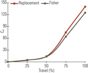
7. Replicant fails lab tests. The laboratory test data show that flow through the valve begins to diverge at about 50% valve opening. When these lines diverge above 50%, the flow rate through the valve rises, as does the potential for cavitation damage. The laboratory testing also showed that the cage material is not uniformly hard, further increasing the potential for damage caused by cavitation in the valve. Source: Fisher Division, Emerson Process Management
Stick with What Works
The use of this particular trim set poses a problem, but the severity of the problem depends greatly on the service conditions to which the control valve will be subjected. Certainly, the pressure drop staging could pose reliability concerns, and the inadequate cage hardness makes those concerns all the more real.
The fact that all of the cavitation holes on the ID of the cage are incorrect is an indication of an inept attempt to copy a precisely machined product. The poor heat treatment of the cage is another sign of low quality. The average hardness of ~22 HRC is just too soft for service conditions where cavitation is a possibility.
The hardness variations and the staging differences combined are factors that could impact both performance and reliability if the replicator’s cage assembly were actually installed in a severe-service valve. The use of this cage almost certainly would result in a short trim set life span, leading to possible valve body damage and expensive repairs.
— Contributed by Josh Crompton, Fisher Division, Emerson Process Management.