Feedwater heaters are used to preheat boiler feedwater by condensing steam extracted from several stages of the steam turbine. Feedwater heaters enhance the thermal efficiency of the power plant by reducing the amount of fuel burned in the boiler to produce a specified power. At the same time, the steam energy extracted from the turbine by the feedwater heater helps to reduce the rate of energy rejection to the environment via the condenser.
Steam extracted from the turbine for feedwater heating is condensed on the shell side of the feedwater heater. The hot condensate collects in the shell and drains to the next lower pressure heater or condenser. A level control valve and piping maintains the proper condensate level in the shell. The condensate level control in the heater shell is very important. High condensate levels can adversely affect steam turbine operation, while low levels can cause steam blow-through, damaging the heater internals and drain piping.
This article explores the complexities and key issues associated with selecting the proper pipe sizing/layout and control valve design that must control hot condensate flow from the feedwater heaters. The biggest challenge occurs when hot condensate flashes to steam as pressure decreases in the drain piping. The flashed steam produces a two-phase flow mixture that can restrict flow in the drain system and thus upset operation of the heater shell level control. The flashed steam can also erode the control valve internals and drain piping.
Complex Heater Design
The feedwater heater shell can comprise up to three separate zones within the shell: the desuperheating, condensing, and drain cooling zones. First, the incoming superheated steam enters the optional desuperheating zone, where it is reduced in temperature until reaching saturated conditions. Next, the steam enters the condensing zone, where the saturated steam changes state, at the saturation temperature, to become saturated liquid. Finally, steam condensate enters the optional drain cooling zone, where it is subcooled below the saturation temperature by the incoming feedwater.
In multizone heaters, the normal heater drains are connected to the outlet of the drain-cooling zone and therefore are capable of handling subcooled condensate. The normal drains are routed through a level control valve to the next lower pressure heater, which also improves the cycle efficiency. In contrast, emergency drains are typically connected to the condensing zone, where they discharge condensate at saturated temperature and pressure conditions through a separate line and level control valve directly to the condenser. The drains from the lowest high-pressure (HP) heater in the typical Rankine cycle are routed to the deaerator.
Many Complex Calculations
Maintaining the proper condensate level in the heater shell is critical. Therefore, the heater drain level control valve and piping system must be adequately designed to discharge the hot condensate flow across the specified operating range of the plant. Guidance and commentary on how to complete a successful design is provided in the remainder of this article. See the sidebar “Step-by-Step Calculation Procedure” for a summary of the discrete calculation steps described in the article.
Review Drains from Feedwater Heater to Level Control Valve
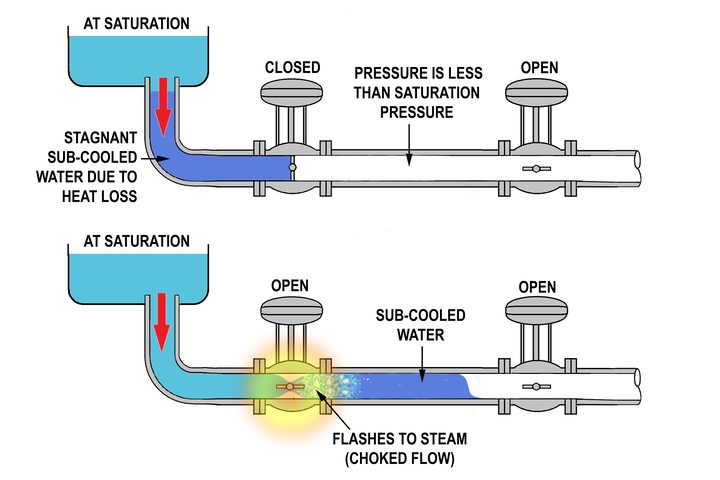
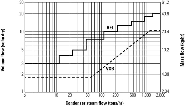
The drain piping upstream of the level control valve should be designed to handle single-phase condensate without steam flash. For proper operation, the drain should be adequately subcooled to prevent steam flashing when line pressure decreases due to frictional pressure drop or elevation change (upward-rising pipe). The frictional pressure drop is minimized by using guidelines such as the Heat Exchange Institute (HEI) criterion of heater nozzle velocity not exceeding 4 ft/sec at operating temperature. However, the velocity-based design approach should be verified and revised, if necessary, by ensuring that line pressure after elevation and frictional change does not drop below the saturation pressure.
The pressure loss caused by increasing elevation (upward-rising pipe) is ideally minimized by placing all HP heaters side by side on the same elevation in the plant and the low-pressure (LP) heaters side by side on a lower elevation. However, the deaerator must be installed at a much higher elevation because of the boiler feed pump’s net positive suction head requirements. Therefore, when the lowest HP heater drains to the deaerator, the drain line pressure change due to elevation becomes significant. For example, the lowest pressure HP heater must drain from a low elevation (say, 7 meters) to the deaerator at a higher elevation (say, 30 meters), thus making the elevation difference (30 – 7 = 23 meters) very significant.
Elevation differences are particularly important at part-load operation, when the differential operating pressure between the HP heater and the deaerator decreases. In this case, the level control valve should be located so that the line pressure does not drop below the saturation pressure for all operating cases upstream of the level control valve. Otherwise, the control valve flow capability will be significantly reduced and the potential for erosion in the piping system will increase.
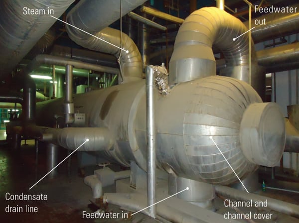 |
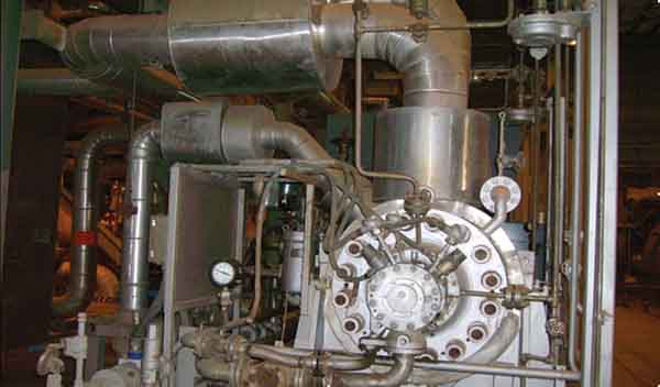
| 1. Go with the flow. A typical feedwater heater with condensate drain lines is shown. Courtesy: Bechtel Power Corp. |
Calculate Pressure at Drain Piping Exit Downstream of Level Control Valve
The drain piping downstream of the level control valve can handle single-phase flow or two-phase flow, or the initial part of the drain flow can be single phase, changing to two phase farther downstream.
In all cases, the pressure drop in the piping can include significant static head, which must be considered in determining the control valve outlet pressure (P2). Of course, the static head is much larger for single-phase flow due to the presence of the fully liquid column downstream of the control valve.
Single phase is promoted by subcooling condensate in the upstream heater drain cooler. In drain piping downstream of the control valve, single-phase flow is indicated when critical exit pressure is found to be higher than the saturation pressure.
The pressure in the drain piping exit downstream of the control valve depends on whether this section has single-phase, two-phase nonchoked, or two-phase choked flow. The critical pressure at the exit is required to determine if the flow is choked or nonchoked.
Technical literature provides several methods for calculating this critical pressure. One useful methodology is based on the homogeneous equilibrium model (HEM) for two-phase flow and involves simultaneous solution of energy and momentum conservation equations. That is the approach used for calculating critical pressure in this article.
This critical pressure at the exit (Pce) corresponds to choked flow at the downstream heater inlet based on pipe diameter, flow rate, and saturation pressure (Psat) of the fluid at the temperature it leaves the upstream heater. As discussed below and shown in Figure 2, Pcecan then be compared against Psatand against the downstream heater pressure (P2dh) to select the correct pressure at the exit.
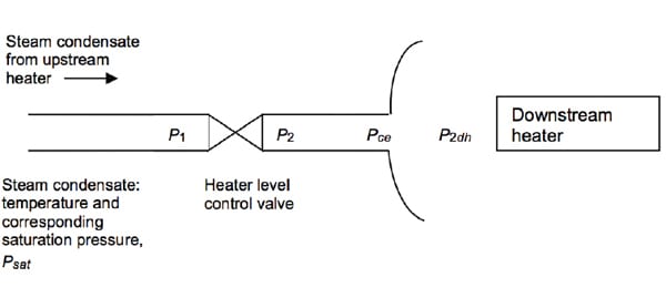 |
| 2. Pressure points. Locations of drain line pressures referenced in the article are shown. Courtesy: Bechtel Power Corp. |
Once the pressure at the exit is determined, the pressure gradient is calculated working backwards from the drain piping exit at the downstream heater toward the level control valve outlet, considering single-phase flow or two-phase flow (using HEM), as applicable.
There are three scenarios to be considered when determining the end receiver inlet pressure:
- If Pce > Psat, then there can be no steam flash, and the entire section of drain piping downstream of the level control valve must be treated as having single-phase flow. In this case, Psat is considered as the end receiver pressure and the single-phase pressure drop worked backwards to establish the control valve outlet pressure P2.
- If Pce < Psat and Pce > P2dh, then steam flash is occurring (under choked flow conditions) and the section of drain piping downstream of the level control valve must be considered as having two-phase flow. In this case, Pce must be used as the end receiver pressure instead of P2dh. The two-phase pressure drop is then worked backwards to establish the control valve outlet pressure P2.
- If Pce < Psat and Pce < P2dh, then steam flash is occurring (under nonchoked flow conditions) and the section of drain piping downstream of the control valve must be considered as having two-phase flow. However, in this case P2dh can be used in the flow calculation as the end receiver pressure. The two-phase pressure drop is then worked backwards to establish the control valve outlet pressure P2.
Calculate Control Valve Outlet Pressure
If there is no condensate flash, the section of drain piping downstream of the level control valve (up to the downstream heater) must be treated as single phase. In this case, the conventional Darcy equation can be used for liquid condensate pressure drop calculations using Psat as the downstream heater pressure. This calculation, along with adjustments for static head and velocity head, will establish the control valve outlet pressure.
If condensate flash is present, the fluid in the section of drain piping downstream of the level control valve (up to the downstream heater) must be treated as two-phase flow. In this case, the general flow equation (modified Bernoulli equation) can be used to determine the upstream pressures starting with small pipe sections backward from the receiving heater:
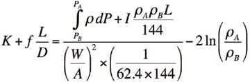
Where, K = piping component resistance coefficient; f = friction factor; L = piping equivalent length, ft; D = piping diameter, ft; I = 0 for horizontal pipe, +1 for vertical pipe (down flow), or −1 for vertical pipe (up flow); W = flow, lb/sec; A = pipe area, ft2; ρ = density, lb/ft3; P = pressure, psia; subscripts A and B represent the upstream and downstream conditions, respectively.
The integral expression can be approximated as (PA– PB)(ρA+ ρB)/2 for small pipe sections and the general flow equation used in several steps to cover the downstream piping.
The general flow equation can be used to establish the upstream density ρ1 and the corresponding pressure P1 and is best executed with commercially available computer software. However, if software is not available, this equation is still fairly manageable using a spreadsheet program.
Because the downstream receiving heater pressure P2dh (or the critical pressure at the exit in the case of choked flow) and saturation pressure Psat are known, the amount of steam flash can be computed. Knowing the amount of steam flash, the density of liquid vapor mixture ρB can be evaluated at the downstream point. For the upstream point, a trial and error method can be used by selecting a value of P1, then calculating P1/Psat and corresponding steam flash and corresponding density ρA. The density values are then used in the general flow equation and the process is repeated for ρA until the equation balances.
The two-phase mixture density (based on HEM) can be computed from the quantity of steam flashed as follows: ρMIX = (WG+ WL)/(WG/ρB + WL/ρB), where WG and WL are flashed steam and condensate flow rate in units of lb/hr, respectively and ρG and ρL are steam and condensate density in units of lb/ft3, respectively,
In the special case where the downstream piping has varying piping diameters (such as a reducer attached to the control valve), the critical pressure at the exit should be evaluated for the different diameters. If Pce at the smaller end of the reducer works out to be greater than the saturation pressure, then the flow is liquid at the valve outlet (and the pressure should be set at the saturation pressure).
The key to sizing and selecting the best control valve is establishing the correct value of P2. The control valve sizing selection also involves determining the pressure at the control valve inlet P1, but this value is fairly simple to calculate because it is based on single-phase liquid flow.
Check Heater Drain Valve Cavitation/Flashing Conditions
The heater drain control valve may be subject to cavitation or flashing service, which could damage valve internals and piping. It is therefore important to establish clearly whether the valve is subject to cavitation or flashing so the appropriate mitigating methods can be used.
The heater drain control valve sizing depends on the allowable pressure drop (ΔPa) across the valve. The allowable pressure drop is the smaller of the actual pressure drop and the choked pressure drop.
The choked pressure drop, for valves installed without inlet/outlet fittings, can be predicted by the following equation: ΔPchoked= FL 2x (P1– FFPv), where FL= liquid pressure recovery factor provided by valve manufacturer; P1= upstream pressure at valve inlet, psia or kPa; FF= liquid critical pressure ratio factor = 0.96 − 0.28SQRT(PV/PC); PC= critical pressure of liquid, psia or kPa; and PV= vapor pressure of the liquid at flowing temperature, psia or kPa.
The choked pressure drop corresponds to choked flow in the valve created by the formation of gas bubbles when the fluid pressure drops below the vapor pressure at the valve vena contracta. The formation of gas bubbles at the valve vena contracta depends on the downstream pressure (P2), meaning the valve could be in cavitating service or flashing service.
Consider Effects of Cavitation
Cavitation occurs in the valve only in single-phase liquid service across the valve. As the liquid flows through the control valve, the pressure falls from the inlet pressure until a point is reached when the local fluid pressure falls below the vapor pressure. At this point, vapor bubbles are formed. The potential for cavitation damage occurs when the downstream pressure (P2) again rises above the vapor pressure and the vapor bubbles collapse.
As mentioned previously, if the actual pressure drop is higher than the choked pressure drop, the choked pressure drop is the allowable pressure drop for control valve sizing. However, at these conditions, fully developed cavitation can be expected with its high potential for damage to valve internals and downstream piping.
If the actual pressure is less than the choked pressure, the actual pressure is the allowable pressure for control valve sizing. But, to establish the damage potential from cavitation, this value of actual pressure drop must be compared to the ΔP associated with the cavitation index provided by the valve manufacturer. Instead of the cavitation index, some valve manufacturers use the cavitation coefficient, calculated as KC= ΔP x (P1– Pv). The cavitation coefficient KC assumes that a valve may function without damaging cavitation at any pressure less than the pressure drop calculated using the coefficient.
Another commonly used cavitation index (σ) is defined by the Instrument Society of America (ISA) in publication ISA-RP75.23-1995, where σ = (P1– Pv)/(P1– P2).
The valve manufacturer can provide the minimum recommended value for sigma at various conditions, including incipient cavitation, onset of damaging cavitation, or manufacturer’s recommended value. These values may need to be adjusted for pressure scale effect (PSE), size scale effect (SSE), and pipe reducer effect (defined in ISA-RP75.23-1995) in case the reference conditions used for establishing σ differ from the service conditions. The adjusted value of σ under service conditions may be higher than the manufacturer’s recommended value (after adjustments for PSE, SSE, and pipe reducer effect).
Based on the above considerations, cavitation in control valves can be mitigated by two methods:
- Modify system operating conditions so that either valve outlet pressure remains below the vapor pressure, thus creating only flashing conditions but no cavitation, or minimize valve pressure drop so that σ exceeds the valve manufacturer’s minimum recommendation.
- Use multistage trims or anticavitation trim in the control valve. This type of trim divides the overall pressure drop into several stages, thus preventing the pressure at the vena contracta of any individual stage from falling below the vapor pressure. Some flashing service damage can be minimized by use of hardened trim material or upgraded metallurgy for valve body and use of target flanges in the downstream piping.
Finally, if the downstream pressure is lower than the vapor pressure at the flowing temperature of the fluid, the fluid will flash, resulting in a vapor-liquid mixture. This mixture moving at high velocities often causes erosion in the valve internals and downstream piping. Some flashing damage can be minimized by use of hardened trim material or upgraded valve body metallurgy and use of target flanges in the downstream piping
Additional Design Considerations
Designing heater drain piping and the associated control valve is complex and requires careful evaluation to ensure that the heater drains function properly and are capable of passing the required flow over the intended range of operation. To aid the engineer responsible for checking the adequacy of the design, use the checklist provided in the sidebar “Design Review Checklist.” By following this procedure you can be assured of producing a robust design that will operate under all expected plant operating conditions for many years.
—S. Zaheer Akhtar, PE is the assistant chief & technical advisor to the PGESCo manager of engineering, on assignment from Bechtel Power Corp. to PGESCo, Cairo, Egypt.