Every power engineer must have a firm grasp of the rudiments of how fuel is processed to produce electricity in a power generation facility. With this article, we begin a series of Power 101 tutorials that present these fundamentals in a clear and concise way. First up are the essentials of recovering heat from flue gas.
The major operating cost of a coal-fired power plant is for fuel. Given the higher heating value (HHV), the amount of coal required to generate a desired power output depends on unit efficiency (net unit heat rate). Therefore, unit efficiency is an important economic factor, and recovering heat from the stack gas will further improve the plant economics.
Some Preliminaries
A relationship between the net unit efficiency and net unit heat rate (HRnet) is presented in Figure 1. [Download this ppt file to view all figures at a legible size.] Thermal efficiency, or efficiency (η), is defined as the electric energy output as a fraction (or percentage) of the fuel energy input. Heat rate is an inverse of efficiency (multiplied by the unit conversion factor of 3,412). Both the efficiency and heat rate can be expressed on an HHV or a lower heating value (LHV) basis. In the U.S., HHV is used for the coal-fired power plants, while in Europe, efficiency calculations are based on LHV. A recent article in POWER provided a comprehensive discussion of power plant efficiency. Bottom line: Be careful when comparing efficiencies from different data sources. To avoid confusion, a note “on HHV basis” or “LHV basis” should be added next to the numerical value of efficiency or heat rate.
Reference also is often made in the literature to changes in efficiency by percentage points (%-points), which should be distinguished from relative changes in percentage. For example (Figure 1), a change of 1%-point in efficiency (from 36% to 37%) represents a relative change of 2.7%. The difference in efficiency between HHV and LHV for bituminous coal is about 2%-points (5% relative), while for the high-moisture subbituminous coals and lignites, the difference is about 3% to 4 %-points (8% to 10% relative, depending on the coal composition).
Besides lower fuel cost, reduced fuel use results in lower emissions of NOx, SOx, Hg, PM, and other pollutants. Efficiency improvement, as the only practical option for reducing CO2 emissions in the short term, has become a key consideration when choosing technology for new plants and for upgrades of existing power plants. A relationship between heat rate improvement and reduction in CO2 emissions, presented in Figure 2, shows that CO2 reduction is proportional to the heat rate improvement. That is, 1% improvement in heat rate results in 1% reduction in CO2 emissions, regardless of the coal type or its rank.
Savings in the fuel and CO2 emissions cost for a typical 580-MW power plant firing Illinois coal are presented in Figure 3 as functions of the heat rate improvement and cost per ton of CO2 over an assumed range of carbon allowance prices. The results show that 1% improvement in net unit heat rate (on a relative basis) results in annual fuel savings of $1.6 million, assuming an energy cost of $4/million Btu (MBtu) and unit capacity factor of 85%. With a CO2 cost of $30 per ton, annual savings are almost doubled ($2.8 million/year).
The efficiency of a coal-fired power plant also will have a strong effect on the cost of carbon capture; with higher efficiency, the flow rate of flue gas that needs to be treated will be lower, resulting in a smaller and less-expensive carbon capture and sequestration (CCS) system. A smaller CCS will have smaller negative effect on plant efficiency.
There are numerous opportunities and options for improving the efficiency of existing power plants. Utilization of waste heat for boiler efficiency improvement, improvement of steam turbine cycle heat rate, and stack reheat are described below. Boiler efficiency improvement achieved by using heat recovered from the flue gas for drying of high-moisture and washed coals will be discussed in Part II. The improvement in steam cycle performance achieved by using heat recovered from the flue gas for feedwater heating and preheating of combustion air will be discussed in Part III.
Heat Recovery from Flue Gas
The temperature of the flue gas leaving the boiler is commonly reduced in an air preheater (APH) when the sensible heat in the flue gas leaving the economizer is used to preheat combustion air. Preheating of combustion air has a significant positive effect on boiler efficiency. Common practice is to recover sensible heat from flue gas until the temperature of the flue gas drops to approximately 300F. The primary impediment to recovering heat by additional cooling is the risk of condensing sulfuric acid on the APH heat transfer surfaces and downstream ductwork.
Acid deposition leads to corrosion of affected surfaces, as well as to fouling and plugging of the APH heat transfer passages. The APH fouling increases pressure drop across the APH (both on the air and flue gas sides), which increases power requirements for the forced draft (FD) and induced draft (ID) fans, resulting in higher station service power and higher net unit heat rate (lower net unit efficiency). Higher pressure drops also lead to higher pressure differentials between the air and flue gas streams, which result in higher air-to-flue gas leakage. Higher leakage increases fan power requirements and increases the flow rate of flue gas through the pollution control equipment.
Sulfuric acid in the flue gas is formed in gas-phase reactions of SO3 and H2O upstream of the APH. The SO3 is formed from SO2 by homogeneous and heterogeneous reactions in the furnace and convection pass of the boiler. The presence of SO3 in the flue gas increases the dew point of the flue gas. The acid dew point temperature is presented in Figure 4 as a function of the SO3 and H2O concentration in the flue gas. Sulfuric acid condenses as temperature is decreased bellow the dew point temperature. The condensed sulfuric acid (acid and water mixture—sulfuric acid is hydroscopic) is corrosive to the inexpensive materials used in construction of the APH heat transfer surfaces and downstream ductwork. Heat rate improvement that could be achieved by increasing heat transfer in the APH is typically inadequate to justify higher-cost corrosion-resistant materials that would be needed for the APH cold end, electrostatic precipitator (ESP), and the ductwork, and to deal with higher APH fouling and plugging.
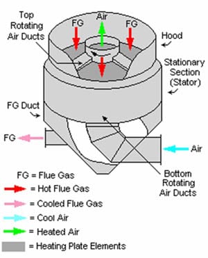
Assuming the SO3 concentration in the flue gas of 5 ppm and bituminous coal (H2O concentration in the flue gas of 8% by volume) gives the acid dew point temperature of approximately 263F. It has to be noted that although the flue gas temperature at the APH exit is typically 50F or more above the acid dew point temperature, metal surface temperatures could be below that, as in the case of the Ljungstrom APH. In a Ljungstrom APH, temperature of the heat transfer surfaces located in the cold end layer of the APH are controlled by the inlet air temperature and are significantly lower than the acid dew point temperature. More details on the APH heat transfer, performance, and fouling and plugging will be presented in Part II.
Besides acid deposition, the other impediment to recovering heat from the flue gas by additional cooling in the APH is the ESP performance. As presented in Figure 5, resistivity of flyash decreases as the flue gas temperature is reduced below 300F. However, in case of the high-resistivity ash (Figure 5), the temperature reduction would not be a problem, for the low-resistivity ash low flue gas temperatures will have a significant negative effect on the ESP performance.
Steam generators that employ ammonia injection for selective catalytic reduction (SCR) or selective noncatalytic reduction (SNCR) of NOx encounter an additional challenge in design and operation of low-temperature heat-recovery equipment, particularly APHs. Unreacted ammonia combines with SO3 in the flue gas stream and SO3 produced on the SCR catalysts to form ammonium bisulfate (ABS). The ABS forms in a temperature range between the APH flue gas inlet and outlet temperatures. The deposits are sticky and corrosive to steels commonly employed in the APHs.
Upon exiting the ESP, it is common to cool the flue gas by evaporative cooling to a temperature close to the adiabatic saturation temperature by spraying water into the flue gas stream within a wet flue gas desulfurization (FGD) system. According to an FGD manufacturer, the optimal flue gas temperature for a desulfurization process is approximately 149F (65C). Cooling of the flue gas to the saturation temperature occurs in a spray area, and the flue gas leaves the FGD reactor at a temperature close to the saturation temperature. In same cases, the flue gas is leaving the FGD in a supersaturated state with a temperature slightly below the saturation temperature. This practice results in significant use of water for evaporative cooling. More importantly, the sensible heat of flue gas is not beneficially used.
Saturation temperature is a function of the moisture content in the flue gas, which depends on the total coal moisture (TM) content of coal, and humidity of inlet air. The moisture content of the flue gas is presented in Figure 6 as a function of the total coal moisture content. Calculations were performed for the excess air coefficient (E) of 17.2% and humidity of inlet air of 0.01149 mole H2O/mole air.
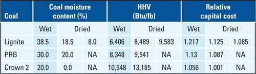
The flue gas moisture content and saturation temperature for the bituminous and washed Illinois coals, subbituminous (Powder River Basin, PRB) coals, and lignites are summarized in Table 1. The saturation temperature is presented in Figure 7 as a function of TM. For these coals and combustion conditions, saturation temperature varies in the 104F to 134F range.
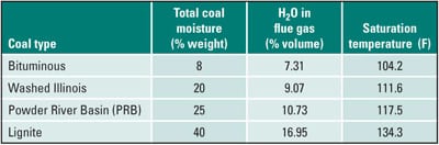
Table 1. Saturation temperature for various coals. Source: Energy Research Center
Low-Temperature Heat Recovery
The amount of heat available in the flue gas is presented in Figure 8 as a function of the flue gas temperature for four coals: bituminous, washed Illinois, PRB, and lignite. Washed Illinois coals contain significant amount of moisture (18% to 22%, or more), which reduces its HHV value. Most of this moisture is surface moisture, which can be removed by drying. As the flue gas temperature is reduced, the amount of available sensible heat increases. The sensible heat that could be recovered from the flue gas by cooling it in a flue gas cooler (FGC) from the APH gas outlet temperature of 310F to the FGD inlet temperature of 140F is 43 to 46 Btu per pound of flue gas (depending on the coal type).
As the flue gas is cooled below its saturation temperature, flue gas moisture condenses to maintain partial pressure of the water vapor in flue gas that is consistent with the flue gas temperature, and water vapor content of the flue gas decreases (Figure 9). The amount (mass) of condensed water increases as the temperature of the flue gas is reduced and is a strong function of the coal moisture content.
As moisture condenses out of the flue gas steam, the flow rate of flue gas decreases, causing a slight decrease in the amount of sensible heat in flue gas (Figure 8). The kink in the sensible heat curve occurs at the saturation temperature of flue gas.
As shown in Figure 9, most of the moisture can be removed from the flue gas by cooling it to a very low temperature. The chilled ammonia concept, developed by Alstom Power, employs cooling of the flue gas to a very low temperature using chillers. At the current state of technology development, such low-temperature cooling of the flue gas is expensive due to high power requirements for the chillers.
Condensation of the flue gas moisture liberates latent heat. The amount of latent heat released is a function of the flue gas temperature and coal type (Figure 10). The amount of released latent heat increases as TM content of the coal increases and temperature of the flue gas decreases. The latent heat can be recovered in condensing heat exchangers (CXEs), but due to the low temperature of a cooling fluid, there are practical temperature limits (approximately 100F to 110F) that impose limits on the amount of latent heat than can be economically recovered from the flue gas. Available heat sinks limit the amount of low-temperature heat that can be beneficially used.
The total (sensible and latent) heat of the flue gas is presented in Figure 11. As the flue gas is cooled below its saturation temperature, the amount of total heat greatly increases. However, as discussed previously, there are practical limitations associated with cooling of the flue gas to low temperatures and beneficial use of the recovered low-temperature heat.
To illustrate total amount of heat available in the flue gas, sample calculations were performed for a conventional supercritical pulverized coal-fired power plant and four different coals. The gross power output of a 642.18-MW, turbine cycle heat rate (HRcycle) of 7,467 Btu/kWh (ηcycle,gross = 45.69%), APH leakage of 10%, flue gas temperature at the boiler outlet of 680F, and coal TM content from Table 1 were assumed in the calculations. The results are presented in Table 2 and Figure 12. The sensible heat was determined for the case where the flue gas is cooled in a FGC located upstream of the FGD from a temperature of 310F (APH gas outlet) to 140F (FGD inlet).

Table 2. Baseline power plant. Source: Energy Research Center
The total heat (including latent heat) was determined for the case where the flue gas was cooled in the FGC and CXE from a temperature of 310F (APH gas outlet) to 110F (inlet to a CO2 absorber). Flue gas cooling down to about 110F will be needed for efficient operation of the post-combustion CO2 capture system (CO2 absorber). Even deeper cooling is needed for the chilled ammonia process.
The results show that for low-moisture bituminous and washed Illinois coals having low saturation temperatures, the benefit of cooling the flue gas down to 110F is small. As TM content of the coal increases, such for the PRB and lignites, the amount of total heat increases significantly, especially for the lignites. Therefore, for high-moisture coals it might be economical to recover the low-temperature heat. This is not the case for the low-moisture coals, where cooling of the flue gas in a FGC upstream of the FGD is most economical option.
Feedwater Heating and Combustion Air Preheat
The technology to recover low-temperature heat from flue gas originated in Europe, where it has been used to improve performance of coal-fired power plants and industrial plants for more than 15 years. Utility companies such as RWE Power, Vattenfall, and others utilize the low-temperature heat from flue gas for feedwater (FW) heating and preheating of combustion air. Several different configurations with different commercial names, such as Powerise, were developed and successfully used at power plants such as Schwarze Pumpe, Mehrum, Niederaussem, Lippendorf, and Werndorf in Germany; Voitsberg in Austria; and at other locations, including industrial plants and waste-to-energy plants, such as Vestforbraending in Denmark, where recovered low-temperature heat is used for district heating.
Typical configurations for using low-temperature heat from the flue gas include configurations allowing FW heating and preheating of the combustion air. The low-temperature heat is recovered from the flue gas using the flue gas cooler (FGC) located upstream of the FGD. A configuration was developed for post-combustion CO2 capture retrofit or new construction, where the flue gas is cooled to the 105F to 110F range. This configuration includes the FGC upstream of the FGD and a condensing heat exchanger (CXE) downstream of the FGD and upstream of the CO2 absorber. Let’s estimate the performance benefits achieved by using recovered low-temperature heat.
To illustrate the benefits of using heat recovered from the flue gas for the FW heating, and preheating of combustion air, analyses were performed for a baseline power plant configuration presented in Figure 13 and three coals: washed Illinois, PRB, and lignite. The baseline configuration is a conventional coal-fired power plant employing a boiler, steam turbine cycle with seven stages of regenerative heating of the condensate, and a FGD for SOx control. Temperature of the condensate leaving the main steam condenser is, in this example, 85.9F. Note that the condenser outlet temperature is highly site-specific and depends on the temperature of the cooling water into the condenser, condenser cleanliness, and state of maintenance. Temperature of the cooling water is subject to seasonal variations and location of the plant. For plants equipped with a cooling tower, performance of the cooling tower adds another level of complexity, as its performance is affected by the ambient and process conditions. Combustion air is preheated in a steam air heater (SAH) using steam extracted from the steam turbine cycle. The flow and temperature data presented in Figure 13 correspond to lignite. The results for all three coals are summarized in Tables 3 through 5.
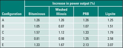
Table 3. Increase in power output compared to baseline shown in Table 2. Source: Energy Research Center
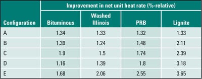
Table 4. Improvement in net unit heat rate compared to baseline shown in Table 2. Source: Energy Research Center
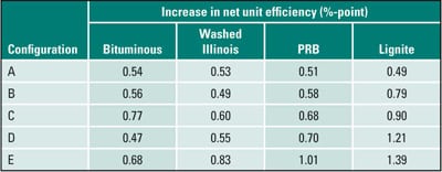
Table 5. Increase in net unit efficiency compared to baseline shown in Table 2. Source: Energy Research Center
The first investigated configuration—Configuration A, for using low-temperature heat from the flue gas, involving a FGC upstream of the FGD—is presented in Figure 14. Instead of using steam extracted from the steam turbine cycle for the combustion air preheat, combustion air is preheated by the heat recovered from the flue gas stream. This increases steam flow through the low-pressure (LP) turbine with a resulting increase in the steam turbine power output. The increase in the turbine power output results in an improvement in turbine cycle heat rate and, ultimately, in the net unit heat rate. One effect was that the heat rejected by the condenser and the condensate flow increased. Also, the amount of heat supplied by the extraction steam and recovered from the flue gas were matched to achieve the same level of combustion air preheat. Finally, the feedwater temperature entering the boiler was kept constant for all analyzed cases.
The second configuration, Configuration B, uses low-temperature heat from the flue gas and includes a FGC upstream of the FGD (Figure 15). One hundred percent of the condensate flow leaving the main steam condenser flows through the FGC, where it is heated. The heated condensate is circulated back to the steam turbine cycle, bypassing low-pressure feedwater heaters (FWH) 6 and 7. This arrangement eliminates low-pressure steam extractions, and the steam that would normally be used in the FWH6 and FWH7 is expanded in the LP turbine. The result is an increase in the steam turbine power output, increase in steam flow to the condenser and main condensate flow, and increase in heat rejected by the main steam condenser. The increase in turbine power output results in an improvement in turbine cycle and net unit heat rates. In this example, the flue gas is cooled to a temperature of 135F. Combustion air is preheated by steam extracted from the steam turbine cycle.
Configuration C represents a combination of Configurations A and B, where a portion of heat recovered from the flue gas is used for FW heating, while the remaining heat is used for the combustion air preheat. A schematic of Configuration C is shown in Figure 16. For clarity, the FGC is divided into two parts, where FGC1 is used for the combustion air preheat and FGC2 is used for the FW heating.
Configurations D and E allow cooling of the flue gas to the 105F to 110F range, which is required for post-combustion CO2 capture. Configuration D (Figure 17) is a variant of Configuration B and incorporates a CXE downstream of the FGD and upstream of the CO2 absorber (indicated as CCS). Sensible heat of the flue gas is recovered in the FGC. The first stage of the condensing heat exchanger (CXE1) is recovering sensible and latent heat from the flue gas. The recovered heat is used for the FW heating. The second CXE stage (CXE2) is used to further reduce the flue gas temperature and decrease the flue gas moisture content.
Please note that the flue gas is exiting the FGD in a saturated or supersaturated state. Reduced moisture content in the flue gas has a positive effect on the efficiency of the CO2 absorption/desorption process. Cooling the flue gas to approximately 105F removes about half of the moisture from the flue gas stream. The recovered heat is very low in temperature and has limited use, such as building heating. The alternative is to use a spray cooler instead of CXE2. However, in such cases the flue gas is entering the CO2 absorber in a saturated or supersaturated state. The high moisture content of the flue gas has a negative effect on the efficiency of the CO2 absorption/desorption process and equipment size. A tradeoff analysis is needed to determine the most cost-effective configuration, and that is outside of the scope of this article.
Configuration E (Figure 18) is a variant of Configuration C. Similar to Configuration D, it employs a FGC and a two-stage CXE. The recovered latent and sensible heat is used for the FW heating and preheating of combustion air.
The results are summarized in Tables 3 through 5 and are presented in Figures 19 through 21 for the cycles discussed above. The potential improvement depends on the configuration and coal type. The heat rate improvement varies from 1.24% to 3.65% relative, considering all configurations. Please note that reductions in CO2 emissions are directly proportional to the heat rate improvements.
For configurations not including the CXE, the improvement is lower, from 1.24% to 3.18% relative, but still significant. The corresponding improvement in net unit efficiency is from 0.51%-points to 1.39%-points considering all configurations. For configurations not employing the CXE, the improvement in net unit efficiency ranges from 0.51%-points to 0.90%-points.
Performance improvements for Configuration A are relatively insensitive to the coal. For Configurations B, C, D, and E, potential performance improvement typically increases with the increase in coal moisture content and is highest for lignites. At another subcritical unit, the higher temperature of the condensate leaving the condenser (105.3F vs. 85.9F) for low- and mid-moisture fuels showed approximately 0.2% lower improvement in net unit heat rate compared to our finding summarized in Figure 20.
In summary, performance improvements achievable by using heat recovered from the flue gas for FW heating and combustion air preheat can be significant and should be considered as measures for improving performance and reducing emissions for existing and newly constructed power plants. For existing power plants, where it is difficult or impossible to raise steam parameters to improve performance of the steam turbine cycle, using heat recovered from the flue gas is an attractive alternative. Optimization of the system configuration—such as temperature of the preheat air leaving the APH and FW bypass (fraction of the FW flow bypassing low-pressure FWHs [100% bypass was used in this work])—is a necessary part of any robust plant design.
More to Come
In Part II, we’ll examine the types of coal-drying technologies available, their performance, and operating economics. In Part III, we’ll look at options for flue gas reheat, feedwater heating, and combustion air preheating.
—Nenad Sarunac (ns01@lehigh.edu) is principal research engineer and associate director at Energy Research Center, Lehigh University. The Illinois Clean Coal Institute funded a portion of this work.