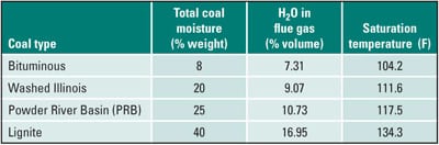
In the flue gas scrubbing process, water evaporates from the scrubbing fluid as the flue gas is cooled to the adiabatic saturation temperature. Under equilibrium conditions, water must be added to the system to make up for the water loss due to evaporation. The flue gas leaves the flue gas desulfurization (FGD) system in a saturated or supersaturated state, carrying a significant amount of moisture, some in the form of water droplets. Some droplets are created by subcooling of the flue gas, while others originate from the scrubbing liquid sprays. Although most water droplets are removed in a demister, some pass through the chevron vanes.
Reheat of the saturated flue gas is needed if velocities in the stack exceed critical velocity (approximately 60 ft/s), which allows water droplets to be carried into the atmosphere with the flue gas, or to increase the buoyancy of the flue gas to ensure adequate dispersion of the residual SO2, NOx, and particulate matter (PM) exiting from the stack. The flue gas reheater can be integrated with the FGD and is typically constructed from spiral-wound finned carbon steel tubes. Heat for the reheater is supplied by the low-pressure steam, extracted from the steam turbine. This steam extraction causes reduction in the steam turbine power output and increases plant heat rate.
Heat displacement technology such as ECOGAVO, ECOCROSS, and ECOSTAT, developed and used in Europe, makes use of heat recovered from the flue gas in a flue gas cooler (FGC) upstream of the FGD for reheating of the saturated flue gas leaving the wet scrubber. The use of extraction steam is eliminated, resulting in higher steam turbine output and improved unit performance. A schematic representation of the heat displacement concept is presented in Figure 1. The numerical values correspond to the washed Illinois coal. (Download this ppt file to view all figures at a legible size.)
Heat recovered from the flue gas in a flue gas cooler is used to reheat saturated flue gas leaving the FGD in the flue gas reheater, in this example to 160F. For the process conditions (flow rates and temperatures) from Figure 1, corresponding to baseline plant configuration and washed Illinois coal, approximately 74 MBtu/hr of heat are needed for the flue gas reheat. This requires flue gas to be cooled from 310F to 258.9F in the FGC. To cool the flue gas to its saturation temperature, 211 klb/hr of water must be evaporated in the FGD. Compared to the no reheat case, this represents water savings of 30%. The evaporated spray water increases moisture content of the flue gas from the inlet level of 9.07% to 14.3% (by volume). For the no reheat case, higher evaporation increases moisture content of the flue gas to 15.9%.
For the assumed SO3 concentration in the flue gas of 5 ppmv and moisture content of flue gas of 9.07% (by volume), the acid dewpoint temperature is 265F. A section of the FGC will, therefore, operate bellow the acid dewpoint temperature (Figure 2). The heat transfer surfaces, operating at or below acid dewpoint temperature, need to be constructed from corrosion-resistant materials, such as corrosion-resistant alloys or corrosion-resistant plastic.
As the flue gas temperature decreases below the acid dewpoint, sulfuric acid condenses, depleting the amount of acid in the flue gas and reducing its concentration. The mass of condensed sulfuric acid is presented in Figure 3 as a function of temperature. Equilibrium calculations were used to obtain results presented in Figures 2 and 3. The amount of condensed acid in this example is small, approximately 24 lb/hr. The sulfuric acid condenses on heat transfer surfaces operating below the acid dewpoint and also as a mist in the flue gas. According to the equilibrium calculations, condensation of sulfuric acid within the FGC reduces the SO3 concentration in the flue gas stream from the inlet value of 5 ppmv to the exit value of 3.5 ppmv.
A variant of the heat displacement concept is presented in Figure 4 where the flue gas is cooled to 160F in the FGC, increasing the amount of recovered heat. The additional heat, representing the difference in heat recovered from the flue gas and the heat needed for the flue gas reheat, is available to be used for the feedwater heating, combustion air preheating, and so on.
Cooling of the flue gas upstream of the FGD to a lower temperature results in lower evaporation within the FGD and less water makeup. Compared to the no reheat case, water savings are almost 80%. Lower evaporation and less water added to the flue gas stream result in lower moisture content of the flue gas at the FGD outlet. With flue gas cooled to 160F, its moisture content is increased in the FGD from the inlet level of 9.07% to 10.8% (by volume).
With lower-temperature flue gas leaving the FGC, a larger portion of the FGC operates below the acid dewpoint temperature, resulting in increased H2SO4 condensation and increased FGC cost.
Another approach to flue gas reheating, employing only one heat exchanger (FGC) is presented in Figure 6. In this reheat arrangement, ambient air is heated in the FGC and mixed with a saturated flue gas leaving the FGD in a mixing box. The advantage of this arrangement is that only one heat exchanger (flue gas-to-air FGC) is needed. Also, flue gas is diluted and flue gas moisture content is lower compared to a conventional flue gas reheat. The disadvantage is that the air added to the flue gas significantly increases the total flow rate through the stack. Also, the size of the FGC will be larger compared to the flue gas-to-water design.
Flue Gas Coolers and Condensing Heat Exchangers
A flue gas cooler is an important piece of equipment, enabling recovery of heat from the flue gas. Because a significant section of the FGC operates below the acid dewpoint temperature, heat transfer surfaces need to be constructed from corrosion-resistant materials, such as corrosion-resistant alloys, carbon steel with a corrosion-resistant coating, high-temperature corrosion-resistant plastic tubing, or borosilicate glass.
The Babcock Borsig Sevices GmbH (BBS) from Oberhausen, Germany, has long experience with the low-temperature heat recovery from flue gas. The low-temperature heat recovery technology Powerise, originally developed by BDT Engineering (Balke-Durr Energietechnik, GmbH), has been used at utility- and industry-owned power plant to improve efficiency and reduce emissions since 1985.
The heat exchanger is built of smooth fluoroplastic Teflon (G-Flon) tubes arranged in a U-tube configuration (Figures 6 and 7). A G-Flon foil lining protects the FGC casing against condensing acid. G-Flon features high resistance to corrosion and reasonable heat conduction transfer characteristics.
Sulfuric acid condenses on surfaces of the heat transfer tubes and the FGC skin, forming a thin layer of diluted sulfuric acid that attracts fly ash and forms deposits. The deposits, forming on vertical heat transfer tubes, are cleaned (washed) by using an integrated water washing system. Wash water and condensed acid are discharged into the FGD. Some acid forms mist in the flue gas stream (Figure 7). Other acids from the flue gas, such as hydrochloric acid and hydrofluoric acid, condense as well, either on heat transfer surfaces or as a mist. Condensation rates of hydrochloric acid, determined by the Energy Research Center, are presented in Figure 8.
Recent design changes to the nonmetallic design at some power generation sites involve application of corrosion-resistant alloys in FGC areas subject to severe acid attack and fouling. This material change has enabled better cleaning of the heat transfer tubes. Plastic tubes in the original heat exchanger design appeared to be flexing in the flue gas stream, making it difficult to remove accumulated deposits by the water-wash system resulting is a higher pressure drop across the FGC. Retrofit with corrosion-resistant alloy tubes has solved the cleaning problem.
Flucorex AG, located in Switzerland, is another manufacturer of corrosion-resistant heat exchangers. The company has been commissioned to supply FGCs for lignite-fired power plants at Neurath and Boxberg, Germany. The heat transfer tubes are made of nickel-based alloy (DIN 2.4605/UNS N06059, trade name “Alloy 59”), corrosion-resistant fluoroplastic, or mild steel tubes double lined with an enamel/glass + PFA. The casing is lined with PFA fluoroplastic sheets.
The gas-to-water WAGAVO exchanger made of Alloy 59 is suitable for applications where HCl and HF concentration is lower than 15 to 20 mg/m3. In cases where HCl and HF concentration is higher, enamel glass-lined plus PFA-lined mild steel is recommended. This double-layer protection, patented by Flucorex, combines zero permeability of enamel with advantages of PFA-plastic lining, i.e. anti-adhesiveness and resistance against HF and strong mineral acid. Tests as well as operating experience have shown that the steel tube is protected even if one of the layers is damaged. The flue gas flows around vertical tubes and water flows trough the tubes.
The gas-to-gas heat exchanger (GAGAVO) with in-line placed plastic tubes in crossflow arrangement is specifically designed for flue gas reheat, Figure 9. Raw flue gas flows inside the tubes from top to bottom, while the clean gas exiting the FGD flows around the tubes. All parts in contact with flue gas are corrosion resistant and made of PTFE, PFA, or nickel-based alloy (Figure 10).
Depending on the plant operating conditions, a water washing system may be installed at the top of the GAGAVO casing. Water washing of the inner surface of the plastic tubes removes any deposits that may form due to the dust load and acid content of the untreated gas. The cleaning system is designed for each particular application and consists of a stationary or retractable water washing lance with several nozzle groups. The washing cycle is programmable to meet plant-specific conditions.
Use of corrosion-resistant plastic or alloy tubes increases the cost of an FGC. As a rule of the thumb, the cost of an FGC operating below acid dewpoint is about 10 times higher compared to the finned tube design employing carbon steels.
Condensing heat exchangers are the subject of intense research and development, not only because of their importance in the oxyfuel process but also for recovering water from the flue gas to minimize water use in a power plant. The electricity industry is second to agriculture as the largest domestic user of water, accounting for 39% of all freshwater withdrawals in the nation, of which 71% is used in fossil fuel–based electricity generation.
A condensing heat exchanger operates at lower temperature compared to a flue gas cooler in order to condense moisture from the flue gas stream. The heat sink temperature, i.e., temperature of the available cooling source, imposes a limit on the amount of water that can be recovered by condensation from a flue gas stream.
Condensation efficiency, the percentage of flue gas moisture condensed out the flue gas stream determined by Energy Research Center for a fixed heat exchanger geometry, is presented in Figure 11 as a function of inlet cooling water temperature (heat sink temperature). The results indicate excellent agreement between the theoretically and experimentally determined values. Condensation efficiency (the percentage of condensed moisture relative to the inlet moisture) increases as sink temperature is reduced. For the sink temperature of 75F, condensation efficiency approaches 80%. Results of theoretical calculations for a range of coals are presented in Figure 12 as functions of the flue gas temperature. Besides the flue gas temperature, condensation efficiency is a strong function of the coal type, which affects the initial moisture content of the flue gas.
The results shown in Figure 12 clearly show that high-moisture coals are prime candidates for water recovery from the flue gas. For low-moisture fuel, water recovery from flue gas by condensation might not be practical option.
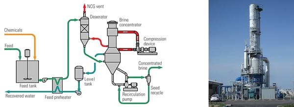
A process for using desiccants to remove moisture from the flue gas has also be proposed. The liquid desiccant dehumidification process involves intimate contact between a liquid desiccant and flue gas. Dehumidification takes place in the absorber tower, where several levels of sprays are used to inject liquid desiccant in a counter-current flow to contact the flue gas. A mist eliminator at the top of the tower is employed to control any entrained desiccant. Water removal from the flue gas ranges from 23% to 63% by volume, with the process conditions dictating the percentage of moisture removed. Higher percentages of moisture removal require higher energy inputs for heating and cooling of desiccant solution. Conceptual layout of the proposed commercial system is presented in Figure 13. Additional development is needed to improve system performance.
A combination of the flue gas condenser and desiccant systems (hybrid configuration) might be a practical option for recovering water from the flue gas. Research concerning hybrid configurations is in progress.
—Nenad Sarunac is principal research engineer and associate director at Energy Research Center, Lehigh University. The Illinois Clean Coal Institute funded a portion of this work.