Cavitation is defined as the phenomenon of forming and imploding vapor bubbles in a region where the pressure of the liquid falls below its vapor pressure. Cavitation and the resultant damage can occur in any fluid-handling equipment, especially in pumps. Technological advances in industrial protective coatings and composite repair materials have made it possible to repair pumps operating in a cavitating environment rather than simply replacing them after damage occurs. Cavitation-resistant (CR) elastomers have the ability to retain adhesion under long-term immersion, dissipate energy created under high-intensity cavitation, and provide outstanding resistance to corrosion and other forms of erosion.
Cavitation is a serious problem for pumps. In simple terms, the main utility of a pump is to move a fluid from one location to another under sometimes very extreme conditions. The impeller vane is subject to pressure gradients, which cause bubbles to form and implode and strike the surface underneath. The resulting damage to the pump’s internal working parts can cause loss of pump performance and even pump failure.
The phase diagram of water in Figure 6 is a practical aid to understanding the theory behind cavitation. This diagram illustrates the three physical states of water at different values of temperature and pressure. Water is most commonly boiled by heating it at a constant pressure, as we do when boiling a pot of water on a stovetop (white arrow). As temperature increases at constant pressure, water remains in a liquid phase until it reaches the normal boiling point (100C at 1 atm).
What is less intuitive is that water can also be boiled by dropping the pressure at a constant temperature (red arrow in Figure 6). This is exactly what occurs just behind the leading edge of a pump impeller vane. As water (or any other fluid) enters the pump, it is deflected by the vane. Above the leading edge of the vane, the fluid is compressed, creating a high local pressure area. Directly after the leading edge, there’s a small area of decreased pressure. If this decrease in fluid pressure moves below the vaporization curve at constant temperature, the fluid will begin to boil, and vapor bubbles will form in the fluid. Behind this low-pressure area there is another high-pressure region. As the vapor bubbles entrained in the fluid move into this high-pressure region, they condense and collapse violently against the surface of the impeller vane. This rapid production of vapor bubbles, followed by their violent collapse, is described as cavitation (Figure 7).
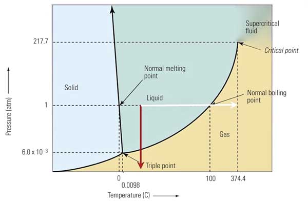
6. Two ways to boil water. The curves on the graph represent equilibrium states. The curve bordering the liquid and gas phases is referred to as a vaporization curve. At normal conditions of pressure and temperature, a fluid is at 1 atm (14.7 psi) and 25C (77F). The white arrow illustrates a typical heating process that occurs at atmospheric pressure. The red arrow illustrates that saturation temperature (hence, boiling) of a liquid can also occur by reducing the liquid’s pressure. Source: Belzona Inc.
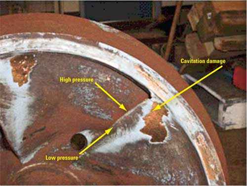
7. How to damage a pump. A cavitating fluid can cause extensive damage to a pump impeller even during normal operation. The imploding pressure caused by cavitation has been recorded as high as 145,000,000 psi, which exceeds the elastic limit of any exotic alloy. These vapor bubbles are responsible for the mechanical damage found on pump impellers placed in any type of service that causes cavitation. Courtesy: Belzona Inc.
One Solution: Upgrade Materials
The easiest solution to problems caused by pump impellers suffering from cavitation lies in finding a material that can withstand the high pressures experienced during cavitation. At the same time, this material must endure harsh environments and be machinable. Unfortunately, there isn’t a single alloy available that meets these strict requirements that is also cost-effective. Most users must settle with either replacing the pump impeller at routine intervals or protecting it with a sacrificial material that is readily available, easy to use, and cost-effective.
A new CR elastomer that can bond to virtually any substrate, including steel, was formulated as a more cost-effective solution. Provided the surface is adequately prepared, adhesion strengths of over 3,200 kg/m2 can be achieved. Combining elastomeric properties and great adhesive strength, the material can withstand full immersion and a harsh working environment. More importantly, the material’s flexible nature gives it the ability to dissipate the enormous energy involved in cavitation as well as in other erosion processes.
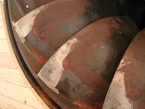
CR fluid elastomer coatings on pumps have been in service for a number of years. In one particular case, the sides and the trailing surfaces of a large impeller had suffered from cavitation and significant metal loss (Figure 8) when a CR elastomer was applied by an authorized coating applicator.
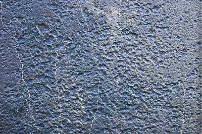
8. Cavitation damage is severe. Close-up of damage to a pump impeller caused by cavitation. Courtesy: Belzona Inc.
The multi-step application process follows:
-
Grit-blast all the surfaces to be coated using an angular abrasive to NACE No.2 (Near White Metal) to a minimum 3 mil (75 µm) angular profile.
-
Thoroughly wash all surfaces with a recommended cleaner degreaser to remove residual blasting debris and contaminants.
-
Mask off the outer edges of the areas to be coated to give a neat and clean finish.
-
If necessary, weld-repair damaged areas or cut out a large section of the impeller and weld in a new plate. Rebuild the substrate to factory specifications using an extended-working-life, paste-grade polymer from a reputable manufacturer.
-
Apply an efficiency-improving, abrasion-resistant polymeric coating using stiff, short bristled brushes to a maximum wet thickness of 10 mil (250 µm) to protect the freshly rebuilt substrate. Two coats of this material are required to ensure that voids are eliminated. This coating is used to prevent the effect of erosion and corrosion under cavitating conditions.
-
Apply a CR coating to the entire impeller (Figure 9).
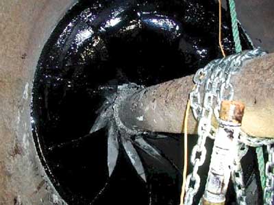
9. Well-dressed impeller. A cavitation-resistant elastomer coating was applied to this pump impeller after the impeller was returned to OEM specifications. Courtesy: Belzona Inc. -
Allow all the coated surfaces to cure, and then inspect the coating for continuity of coverage.
-
Reassemble the pump and put it back into service.
— Contributed by Glenn Machado (gmachado@belzona.com), a technical service engineer for Belzona Inc.