A centrifugal pump that performs well under steady-state conditions may be found to cavitate when transitioning between operating modes. Resolving a transient cavitation problem can seem daunting because many thermodynamic and dimensional factors are involved. This article will help the reader understand the causes of pump transient cavitation, present a simple screening technique for identifying poor designs, and describe what corrective measures to take.
Pump cavitation occurs when a decrease in suction pressure causes the liquid to begin boiling. Vapor bubbles form and violently implode when they enter higher pressure regions of the pump. This creates noise, pitting, erosion, flashing, and vibration. If the bubbles collect and form into a vapor cavity, the pump can experience a water hammer when the cavity collapses. The accumulated damage from these short-term transient events can eventually cause a catastrophic pump failure.
What Is Pump NPSH?
Anyone who has sized a pump should be familiar with the term net positive suction head (NPSH). Simply put, pump NPSH is the excess head (or pressure) exerted on the pump’s suction that keeps the liquid from boiling. The available NPSH (NPSHa) for a pump is given in units of feet-absolute and is defined as follows:
NPSHa = (HP – HVPA) + (HST – HFS)
where HP is the absolute pressure on the surface of the liquid source upstream of the pump converted to head units; HVPA is the pump suction absolute vapor pressure (the pressure at which a liquid at a particular temperature begins to vaporize) converted to head units; HST is the static head on the pump suction (the vertical distance between the minimum liquid level of the source and the pump impeller’s centerline); and HFS is the head loss due to friction in the suction piping at the maximum flowrate. Note that head and pressure terms are often both used when discussing NPSH. Use the liquid specific volume (V) in units of ft3/lb, to convert head in feet to pressure in psi:
psi = feet / (144 x V)
NPSH Margin
The manufacturer determines the required NPSH (NPSHr) for a pump in units of feet-absolute, by steady-state testing the pump with water. NPSHr increases with flowrate, and typically represents the point at which a 3% loss in pump output occurs due to cavitation (called NPSH3). Unfortunately, manufacturers sometimes use a 1% or 0% criterion and occasionally, the pump’s NPSHr curve includes a manufacturer’s margin. If the basis for your NPSHr curve is not clear, the manufacturer should be asked to clarify what it represents.
If the pump is required to provide its full design flow capacity without any cavitation loss, NPSHa must exceed NPSHr by an appropriate margin: NPSHa ≥ margin x NPSHr. The margin required to compensate for a 3% output loss can be calculated as follows:
margin = [(slope x QFW x 3) / (NPSHr x 100)] + 1.0
where the slope of the pump’s NPSHr curve at the maximum pump flow (QFW) is ∆H/∆Q. This margin is typically a factor of about 1.2.
The American National Standards Institute (ANSI)/Hydraulic Institute (HI) standard ANSI/HI 9.6.1-2017 “Rotodynamic Pumps Guideline for NPSH Margin” gives recommendations on how much margin to use based on the pump’s service. Additionally, some engineering firms apply system specific margins based on their experience. For example, when sizing a FW pump, a margin of 1.8 might be used for the design point, and 1.5 at runout.
Note that the margin recommendations do not account for unique operating conditions or equipment arrangements. If there are uncertainties in your design that could increase the potential for transient cavitation, a greater margin would be warranted. Use the largest of the margins applicable for your pump’s service when checking for adequate NPSHa.
Pumps Susceptible to NPSH Transients
A NPSH transient occurs when the variables in the NPSHa expression change during the pumps transition between operating states. Because the variables generally do not change at the same rate, NPSHa might temporarily drop below NPSHr during the transition.
Theoretically, any liquid pump can experience NPSH transients. However, systems that pump low-pressure, high-temperature liquids are most likely to experience problems. Some examples include:
- ■ FW pumps that take their suction from a low-pressure deaerator storage tank containing high-temperature water are strong candidates for experiencing NPSH transients during a turbine load reduction.
- ■ In a combined cycle (CC) power plant there are many variations of deaerator configurations. Some don’t have a separate deaerator, but instead rely on the condenser for deaeration. Some deaerators operate under vacuum conditions. Many stations have a deaerator that is integral to the heat recovery steam generator (HRSG), where the deaerator steam comes from the low-pressure steam drum, not the steam turbine. Some units use pegging steam extracted from the intermediate-pressure steam drum as a backup steam supply for use when turbine extraction steam pressure is low. Because the HRSG is a more stable and reliable source of deaeration steam than the steam turbine, CC FW pumps are generally less likely to experience NPSH transients, as long as the HRSG is correctly operated.
- ■ Heater drain pumps operate with little NPSHa and high temperatures making them susceptible to transients.
- ■ Condensate pumps convey low-pressure, high-temperature condensate from the condenser hotwell. They are not normally susceptible to transients because the large quantity of condensate in the hotwell stabilizes temperature, pressure, and level fluctuations. Also, vertical-can pumps are typically used to provide the submergence needed for sufficient NPSHa.
FW Pump NPSH Transients
A typical FW heating system with overpressure deaeration is shown in Figure 1. The deaerator scrubs out air and heats the FW by direct contact with steam extracted from the steam turbine. It stores a mixture of FW in both the vapor and liquid states. The internal pressure of the deaerator is equal to the vapor pressure of the liquid. This is known as “saturated conditions.” Vapor pressure is a function of FW temperature. The FW temperature and vapor pressure in the deaerator and at the pump suction are the same.
 |
|
1. Simplified schematic of the feedwater (FW, green), condensate (blue), and extraction steam (red) systems in a typical steam power plant. Pump recirculation, FW pump discharge, and low-pressure (LP) FW heater drains are not shown. Source: Michael F. Czyszczewski, PE |
When a steam power plant decreases load, the steam turbine will reduce or stop sending extraction steam to the FW heaters and the deaerator. The pressure in the deaerator will begin to decrease due to the loss of steam pressure, the condensing of steam in the deaerator, and the inflow of colder condensate.
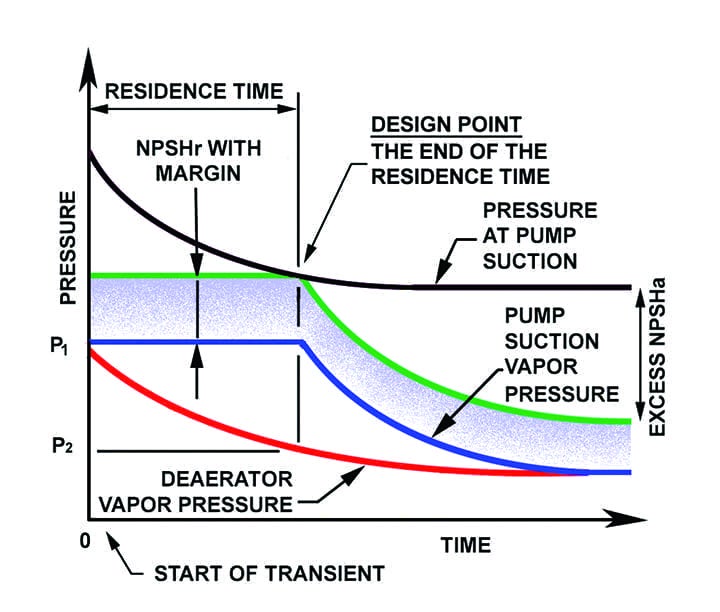
Meanwhile, the mass of FW in the suction pipe acts like a plug to isolate the pump from the temperature and pressure changes taking place in the deaerator. This isolation lasts until the full volume of FW in the suction pipe has a chance to move through the pump and is calculated by dividing the mass contained in the suction pipe by the pump’s mass flowrate. The lag is called the “residence time,” and is illustrated in Figure 2.
 |
|
2. Pressure decay during a net positive suction head (NPSH) transient event. Cavitation occurs when NPSH available (NPSHa) is less than NPSH required (NPSHr). Source: Michael F. Czyszczewski, PE |
The green curve shows the sum of the vapor pressure at the pump and the NPSHr. This is the minimum acceptable pressure head at the pump suction. The black curve shows the actual pressure head at the pump suction (HP + HST – HFS). You don’t want the black curve to fall below the green curve. The intersection of the black and green curves at the end of the residence time creates a design point that can be used to solve for the minimum acceptable deaerator storage capacity.
The Thurston Equation
The subject of NPSH transient formation in FW pumps received a lot of attention by notable pump researchers such as I.J. Karassik and G.S. Liao from the 1950s through the 1970s. Rodney S. Thurston of Cornell University authored a 1961 American Society of Mechanical Engineers (ASME) paper titled “Design of Suction Piping and Deaerator Storage Capacity to Protect Feed Pumps.” In it, Thurston derived a simple expression for evaluating a FW pump’s susceptibility to NPSH transients.
Without going into the details of Thurston’s derivation, he showed that NPSH transient cavitation would not occur if a minimum quantity of FW was stored in the deaerator. By rearranging his equation, a “transient factor” (FT) can be defined where a value equal to or greater than 1.0 indicates an acceptable design. The equation is:
FT = (M / m) x ln[(h1 – hC) / (h2 – hC)]
where M is the mass of FW contained in the deaerator storage tank (lbm); m is the mass of FW contained in the suction piping; hC is the minimum value of enthalpy (Btu/lb) for the condensate entering the deaerator during the residence time; h1 is the enthalpy of saturated water based on the pressure in the deaerator at the start of the transient (P1); and h2 is the enthalpy of saturated water based on the pressure in the deaerator at the end of the residence time (P2). To calculate P2, the following equation is used:
P2 = P1 + (NPSHr – HST + HFS) / (144 x V1)
The liquid specific volume is a function of the saturation pressure in the deaerator at the start of the transient. A high value of P1 will give a more conservative solution; therefore, the safety valve pressure is typically used.
The value assumed for the minimum condensate enthalpy entering the deaerator (hC) is critical to the solution. Colder condensate entering the deaerator will accelerate the pressure decay. Assuming that some of the low-pressure (LP) FW heaters are out of service at the start of the transient adds some cushion to the calculation results. Thurston recommended using the outlet enthalpy of the lowest-temperature FW heater.
If a transient factor of less than 1.0 is calculated, a more rigorous evaluation based on fewer simplifying assumptions may show the design is acceptable. Some tips on performing this evaluation follow:
- ■ Use a pipe flow modeling program to determine the pipe flow head loss.
- ■ Use a spreadsheet to collect the data and perform the NPSHa calculations. The columns should contain the parameters needed to calculate NPSHa over the time of the transient.
- ■ Spreadsheet rows should represent an incremental advancement of time and should cover the entire duration of the transient. Some flow modeling software has the capability to simulate time by combining the results of multiple steady-state runs. This software feature would eliminate or reduce the calculations required with the spreadsheet.
- ■ Steam property functions, which are available for many commercial spreadsheet programs, are needed to simplify the work effort.
- ■ Input data representing the static operating conditions that exist before and after the transient should be per the project heat balances.
- ■ Input a description of how each of the variables that make up NPSHa change during the transient. Ideally, the change rates should be based on instrument data gathered during an actual transient. However, if data is not available, assumptions will need to be made. This typically includes assuming that the liquid enthalpy decay in the deaerator follows an exponential function.
- ■ Plot how NPSHa and NPSHr change over the course of the transient to demonstrate that sufficient margin exists at all times.
For reference, the Thurston equation is based on the following simplifying assumptions:
- ■ The volume of FW in the suction pipe at the start of the transient remains at a constant vapor pressure as it passes through the system.
- ■ All FW leaving the deaerator is a saturated liquid.
- ■ Condensate flowrate into the deaerator equals the FW outflow and is constant.
- ■ There is complete mixing between all fluids in the deaerator.
- ■ No extraction steam flow to the LP FW heaters or deaerator occurs during the transient.
- ■ No FW recirculation or high-pressure heater drain flows enter the deaerator during the transient.
- ■ Heat retention of the pump, piping, deaerator, and FW heater metal mass is neglected.
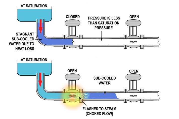
A few additional words concerning the last assumption might be helpful. The metal mass of the pump will tend to store heat after shutdown. The temperature (and vapor pressure HVPA) of the FW it contains will, therefore, be at a higher temperature than the FW in the deaerator. When the pump is restarted, the pressure at the suction will suddenly drop and the hot FW could flash to steam. This differs from a NPSH transient, as the pressure change is initiated by the pump and is, therefore, known as a “hot start” transient event.
An additional steam flashing situation could occur if there are long horizontal runs of suction piping at high elevations. These pipe runs are prone to flashing because there is no increase in static head to compensate for the pressure decay in the deaerator and the friction losses that occur as the FW travels through the pipe. Avoid routing the pipe this way.
FW Pump Transient Solutions
The most commonly recommended options for preventing FW pump transients attempt to eliminate the vapor pressure differential between the pump and deaerator by either cooling the FW at the pump inlet or increasing the deaerator pressure.
Pump Inlet Cooling. NPSHa can be increased by injecting a small amount of cooler condensate near the pump inlet. The most reliable and coldest source of condensate for this is the condenser hotwell. A bypass line can be installed to take a portion (about 10%) of the condensate exiting the hotwell for cooling the pump inlet. The minimum required flow (QB, lb/min) and the new pump inlet temperature (TFW, F) after mixing will be:
QB = [1 – e^(–m / M)] x QFW
and
TFW = T1 + [(QB / QFW) x (TB – T1)]
where TB is the temperature of the bypass source and T1 is the temperature of the saturated FW in the suction pipe before the transient.
The control system can be designed to monitor the deaerator and pump inlet pressures and bypass enough cold condensate, when needed, to lower the pump vapor pressure sufficiently to provide a margin over NPSHr. Other control options are possible. For example, a simpler but less accurate system would be to use a bypass valve with a full open/close actuator that responds to the same turbine signals that control the extraction steam flow to the FW heaters. The bypass would be a low-temperature and -pressure system, which allows the use of carbon steel standard wall pipe components.
The main disadvantage of this option is that it increases the oxygen content of the FW. To minimize this effect, the bypass should be designed for only the minimum flow necessary. Another concern is to ensure the cold condensate injection does not cause high thermal stresses. If this is possible, the injection point should be moved a safe distance away from the pump and a static mixer installed in the suction pipe to insure complete thermal mixing. The mixer must not have a high head loss, as frictional losses will reduce the NPSHa.
Deaerator Pressure Control. The initiating cause of the transient is the deaerator pressure decay that results from the loss of extraction steam. Pump NPSHa can be increased by supplying the deaerator with additional steam to compensate for the loss of extraction steam. The steam drum or the cold reheat system can be used as the supplemental steam source.
The control system can be designed to monitor the internal deaerator pressure and pump inlet pressure. A pressure reducing control valve on the supplemental steam supply line will only admit enough steam as needed to maintain deaerator pressure. This option does not have the oxygenated water, thermal shock, and pressure drop disadvantages of the pump inlet cooling option.
The option’s disadvantages are that robust components suitable for steam service are required. There will also be a very high pressure drop across the control valve requiring a severe service valve be used. The control system will be more complex than that required for the inlet cooling option. For example, in the case of a load reduction, the deaerator pressure must eventually be allowed to drop to the level associated with the new load. Also, the supplemental steam source must also be in an operating state whenever the FW system is operating.
Additional Options. The following options are reliable because they are not dependent on the operation of a control system. However, they can be difficult and costly to implement into an existing installation, or offer only modest gains in NPSHa. Regardless, each situation encountered will be somewhat different, so keep these alternatives in mind:
- Pump Specifications. Confirm the basis for the pump NPSHr curve. Ask the manufacturer what cavitation level basis was used and whether a manufacturer margin was included. Ask the manufacturer to determine the feasibility of pump modifications such as adding an inducer or making impeller material changes to increase its resistance to cavitation. Consider reducing the pump speed to lower NPSH requirements.
- Decrease the Suction Pipe Diameter. Decreasing the mass of FW stored in the suction pipe will create a beneficial decrease in the residence time; unfortunately, it increases the pipe’s flow resistance. Studies have shown, however, that for a small decrease in pipe size, the benefit is usually greater than the penalty.
- Increase the Quantity of FW Stored in the Deaerator. The mass of FW in the deaerator stores heat. Increasing the mass will slow the pressure and enthalpy decay rates. Increasing the deaerator storage capacity usually gives more benefit than decreasing the suction pipe size. If the storage capacity cannot be increased, try raising the low-water level.
- Raise the Deaerator Elevation or Lower the Pump. It is common practice in new plant design to place the deaerator above the pump as high as possible to maximize the static head at the pump suction. Unfortunately, relocating an existing deaerator is unlikely to be practical.
- Reduce the Length of the Suction Pipe. NPSHa is increased by reducing pipe pressure drop. Also, reducing the pipe length reduces the volume of FW in the pipe, which gives the benefit of reducing the transient residence time. Try rerouting the suction pipe to reduce its length, number of valves, and sharp bends. Replace horizontal pipe runs with 45-degree downward-sloping runs, where possible.
- Add a Booster Pump. A low-speed, low-head, single-stage booster pump installed upstream of the FW pump will increase its NPSHa. However, the booster pump will also be susceptible to NPSH cavitation; therefore, it will also need to undergo a transient evaluation.
—Michael F. Czyszczewski, PE (mczyszczewski@asme.org) is a mechanical engineer with 44 years of design experience in the power industry.