Condensation-induced water hammer (CIWH) is the term commonly used when describing a variety of transients that occur when water vapor is rapidly condensed by cold water. This article describes the various types and causes of CIWH, explains how to estimate the velocities and pressures involved, and provides readers with solutions that can be used to prevent it.
Steam and liquid water in a pipeline do not always play well together. Situations where they are unexpectedly brought into contact can be volatile. A hydraulic transient is a short-term event initiated by a rapid change in pipe flow velocity or pressure. The event generates pressure pulses that travel like waves downstream and upstream from their point of origin. The pulses impact and reflect off of obstructions as they travel through the pipe. This produces a hammering noise and kicking-like pipe movements. The term “water hammer” is generically used when referring to these transients even when other liquids and gasses are involved.
Vapor Pocket Formation
Water vapor is wet steam. If you add heat to a quantity of water at the boiling point, it will begin to change (vaporize) from a liquid into a vapor. If you continue to add heat, the liquid and vapor will remain at the same temperature until all the liquid is converted to vapor. This is known as being at saturated conditions. A pipeline that conveys gas and liquid water at the same time is said to contain two-phase flow.
If hot saturated water in a pipe experiences a decrease in pressure, it will begin to vaporize. Small vapor bubbles will form. These bubbles are buoyant so they tend to rise and collect into pockets at high points. Pockets can also be created if the pipe geometry isolates a quantity of steam during a system refill or shutdown. For example, steam can get trapped in a vertical U-bend if both risers become blocked with water when filling.
Vapor Pocket Collapse
A liquid is said to be sub-cooled if it is at a temperature below the saturation temperature for a given pressure. If a vapor pocket comes into contact with a sub-cooled liquid, it will begin to condense at the vapor/liquid boundary. The condensation rate increases as the temperature difference increases. When the temperature difference is greater than about 35F, all of the vapor will suddenly condense. Vapor occupies much more space than a liquid; therefore, a low-pressure void is created. The water surrounding the pocket will accelerate into the void. This implosion occurs in a fraction of a second. The velocity (VI, ft/sec) of the advancing water just before impact is reduced to zero at impact, and can be calculated as shown in Equation 1:
VI = ∆V = √((( 288 gc ( PU – PD )) / ρ ) ( α / ( 1 – α )))

In This Issue
Full issuewhere α is the void fraction (conservatively about 0.5); gc is the gravitational constant (32.2 ft-lbm/sec2-lbf); and ρ is the fluid density (lbm/ft3). The pressure in a vapor pocket (PD) is the vapor pressure corresponding to the temperature of the surrounding water. Because the distance traveled is very small, friction has a minimal effect and is neglected.
The abrupt velocity change generates a water hammer pressure pulse. The velocity of the pulse as it travels through the pipe is the acoustic (sonic) velocity (c, ft/sec), and can be calculated using Equation 2:
c = √(( 144 gc G / ρ ) / ( 1 + ( G / E ) φ ))
where G is the bulk modulus of compressibility of the liquid (psi); E is the modulus of elasticity of the pipe (psi); φ is a pipe boundary condition parameter, which for a thin wall tube fixed at both ends is D/t; where D is the pipe inside diameter (in.); and t is the pipe thickness (in.). Air entrainment would reduce the velocity.
The theoretical maximum pressure pulse (∆P, psi) can be found by using the familiar “Joukowski” water hammer equation, shown here as Equation 3:
∆P = k (( ρ c ∆V ) / ( 144 gc ))
where the variable k is 1.0, if the vapor pocket collapse occurs next to a hard surface such as a pipe dead end or a closed valve, otherwise, k = 0.5. Note that ΔP is not the total pressure, but is the increase or decrease from the steady state pressure that existed before the transient.
Water Slug Formation
When there is stratified two-phase flow in a horizontal pipe, the water level in the pipe will increase due to condensation at the steam/water interface. This decreases the pipe cross-sectional area occupied by the steam, which increases its velocity. When the difference in velocity is great enough, there will be a transition from stratified flow to slug flow. Surface waves will form and move at a higher velocity than the liquid. The waves become bigger as the flow becomes more turbulent. If a large surface wave blocks the pipes cross-sectional area, steam entering the pipeline will exert pressure on the wave’s upstream side, which will propel it down the pipeline as a water slug.
The Froude number (Fr) is a parameter typically used to assess the formation of gravity waves in open-channel flow. Studies have found that there is a minimum velocity (VMIN) above which a transition from stratified two-phase flow to slug flow will not occur. This flowrate corresponds to a Froude number of 0.5. Industry practice is to conservatively use a Froude number of 1.0 when pipe sizing, to provide a design margin. VMIN can be calculated using Equation 4:
VMIN = Fr √( gc D / 12 )
Water Slug Impact
When a water slug strikes something in its path, a water hammer pressure pulse is generated. Neglecting friction, the impact velocity is calculated using Equation 5:
VI = ∆V = √((( 288 gc ( PU – PD )) / ρ ) ( LV / LS ))
where PU is the upstream steam pressure (psi); PD is the downstream void pressure (psi); LS is the length of the slug (ft); and LV is the length of the vapor space (ft).
The pressure pulse at impact (∆P) can be found using Equation 3 with k = 1.0. The slug impact force (F S, lbf) is primarily a function of the slug’s momentum, shown in Equation 6:
FS = ( AP ( ρ VI2 )) / gc
where AP is the pipe internal flow area (ft2). To include the dynamic effects of impact, a conservative dynamic load factor (DLF) equal to 2X is frequently used for design. This factor represents the ratio of stress from a rapidly applied load to the stress that would have occurred had the load been applied slowly.
CIWH Mechanisms
Hydraulic transient events in power plants were extensively studied by the Electric Power Research Institute (EPRI) in the 1970s through the 1990s. Much of the material presented in this article is based on EPRI’s “Water Hammer Handbook for Nuclear Plant Engineers and Operators” TR-106438, which was published in 1996 and can be downloaded from EPRI’s website at: www.epri.com. The study identified and defined the following four basic CIWH mechanisms.
Mechanism 1—Steam Discharging into Sub-Cooled Water. If a steam line discharges under water and the steam flow is stopped by closing an upstream valve, a pocket of vapor will be trapped in the pipe (Figure 1). The water at the pipe exit will begin to cool, because it is no longer being heated by the steam. Contact with sub-cooled water will cause the vapor pocket to rapidly condense. The low-pressure zone created by the implosion causes the water column to be drawn up the pipe and slam into the closed valve at high velocity. A water hammer pressure pulse is emitted at impact. It’s not surprising that this CIWH mechanism is referred to as a water-cannon.
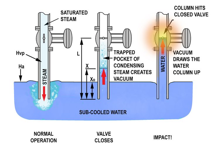
The differential head across the water column (∆H, ft) is found using Equation 7:
∆H = Ha + x0 – HVP
where x0 is the pipe emersion depth (ft); Ha is the pressure head on the water surface; and HVP is the pressure in the vapor pocket.
The water column velocity (VO, ft/sec) is found using Equation 8:
VO = ∆V = √((2 gc ∆H ) / KTotal )
where KTotal is the sum of the “Darcy-Weisbach” component loss coefficients plus (f L) / D. Where, f is the pipe friction factor, L is the distance from the valve to the pipe outlet, and D is pipe inside diameter.
The impact velocity (VI) can be found based on Equation 9, which is an empirical curve fit to data in the EPRI handbook:
VI = VO (( 0.0097 L / ∆H – 0.438) KTotal2 + ( –0.161 L / ∆H + 1.18) KTotal – 0.061 L / ∆H + 1.056)
The impact pressure pulse (∆P) can be found using Equation 3 with k = 1.0.
To prevent Mechanism 1 transients:
- ■ Don’t discharge steam under water.
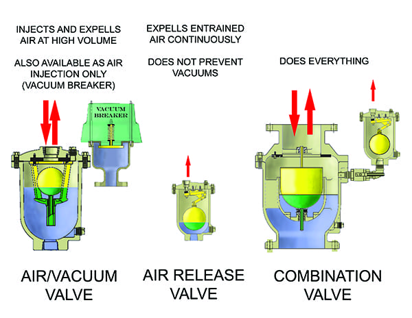
- ■ Add a vacuum breaker below the shut-off valve to inject air into the vacuum space to relieve the vacuum and cushion the water column impact.
- ■ Close the steam shutoff valve slowly.
- ■ Increase the length of the discharge pipe. The height that the water column can climb is limited by the lowest possible pressure in the void.
Mechanism 2—Stratified Steam and Water Counter-Flow in a Horizontal Pipe. This CIWH mechanism occurs in horizontal pipes containing two-phase flow. Figure 2 shows an example where a pipeline is used to supply a steam vessel with sub-cooled water. Initially, the pipe is full of steam. When the fill valve opens, the pipeline starts to fill from the bottom up with water. Vertical pipe sections will run full of water; however, horizontal pipe sections will have two-phase flow with water resting on the bottom surface of the pipe while steam occupies the space above the water.
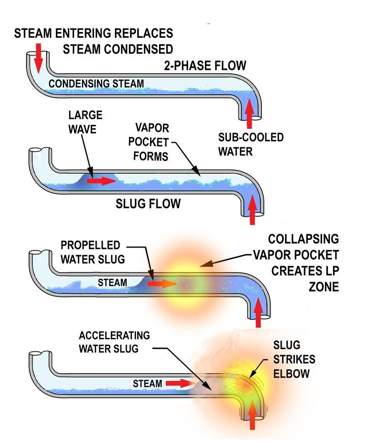
The steam in contact with the water will condense, which will cause more steam to be drawn into the pipe, increasing the condensation and steam flowrates. This initiates a counter-flow pattern between the steam and water, and a transition to slug flow conditions. A large surface wave that fills the pipe cross section will create a vapor pocket on its downstream side. The wave is pushed downstream by steam pressure. The compressed vapor pocket collapses as it comes in contact with sub-cooled water. The implosion creates a water hammer pressure pulse and a large pressure differential across the wave accelerates it down the pipeline as a water slug. When the slug hits a change in direction or a flow obstruction, the impact creates another large pressure pulse.
A mechanism 2 transient can’t occur if the pipe runs full of water. The minimum mass flowrate (m, lbm/sec) to run full of water can be found using the criterion shown in Equation 10, which is based on a Froude number of 0.5:
m ≥ 2.227 ρ D2.5
Also, flow model tests have shown that stratified counter-flow conditions will not form at low flowrates, where the mass flowrate during a water fill meets the criteria in Equation 11:
m ≤ C D2 e–0.005 (LH/D)
where LH is the horizontal pipe length (ft); and C is a coefficient that is a function of pipe diameter (1.5 to 36 inches) given by Equation 12:
C = –0.00001745 D4 + 0.0001736 D3 – 0.06152 D2 + 0.9425 D + 4.280
Counter-flow CIWH has the potential to produce very damaging transient forces. Problems most often occur during startup. Condensate return lines and steam desuperheater spray systems are especially susceptible.
To prevent Mechanism 2 transients:
- ■ Long horizontal pipe lengths will allow the water slug to achieve higher velocity and momentum. Shorten horizontal pipe runs to increase the rate at which they fill, thus minimizing the condensation rate. Pipe runs shorter than 24 pipe diameters are recommended.
- ■ Prevent stratified flow by not adding water to a steam-filled system. Alternatively, ensure that pipes run full of water at all times.
- ■ Transients typically occur when horizontal pipe sections have insufficient slope for drainage. A minimum incline of 0.5 in/ft is recommended to insure the pipe runs full.
- ■ Pipes inclined more than 3 degrees from the horizontal will act like a vertical pipe, and will, therefore, not be vulnerable to Mechanism 2 CIWH.
- ■ Maintain and repair steam isolation valves. Stratified two-phase flow can occur if valves permit steam to leak into and condense in a voided pipe. Similarly, maintain and repair condensate isolation valves. Hot condensate will flash to steam if it leaks through a valve into a lower-pressure pipe.
- ■ Maintain and repair steam traps.
- ■ Keep pipe insulation intact. Heat loss due to missing or insufficient insulation will increase the condensation rate and the severity of the transient.
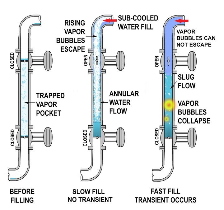
Mechanism 3—Pressurized Water Entering a Vertical Steam Filled Pipe. This CIWH Mechanism occurs in vertical steam-filled pipes or horizontal pipes sloped more than 3 degrees (which act like a vertical pipe). When taking a system out of service, steam can become left behind in pockets. Saturated water can also leak past shut-off valves where it could flash into steam on the low-pressure side and form vapor pockets.
Although condensation plays a role, the primary contributor to the severity of a Mechanism 3 transient is the inertia and pressure of the water filling the pipe, and whether the water enters the vertical pipe from the bottom or from the top.
Top Filling. As sub-cooled water comes into contact with the steam pocket, vapor bubbles will form in the water. If the pipe is filled slowly, the water will primarily flow down the vertical pipe walls (annular-film flow) giving the bubbles a chance to rise in the center of the pipe and escape. However, if the water fill rate is faster than the bubble rise velocity, the vapor bubbles will be trapped, and they will condense and collapse under the pressure exerted by the entering water. Collapsing vapor bubbles are much smaller than a collapsing vapor pocket, so the resulting water hammer pressure pulses are considered moderate, and not severe (Figure 3).
The maximum safe filling velocity (VF, ft/sec) for annular flow in a vertical pipe can be calculated using Equation 13:
VF = 0.67 √((( ρf – ρg ) / ρf ) (( gc D ) / 12 ))
where, ρf and ρg are the densities at saturated conditions for the liquid and gas phases, respectively. Note that when pressures are low, the gas density is near zero, so the density terms can be neglected. Also note, if the pipe is inclined more than 15 degrees from the vertical, the annular flow pattern becomes modified. Vapor bubbles will gather along the upper part of the pipe cross section and their rise velocity will increase, therefore, the safe fill velocity should be increased by a factor of the √2.
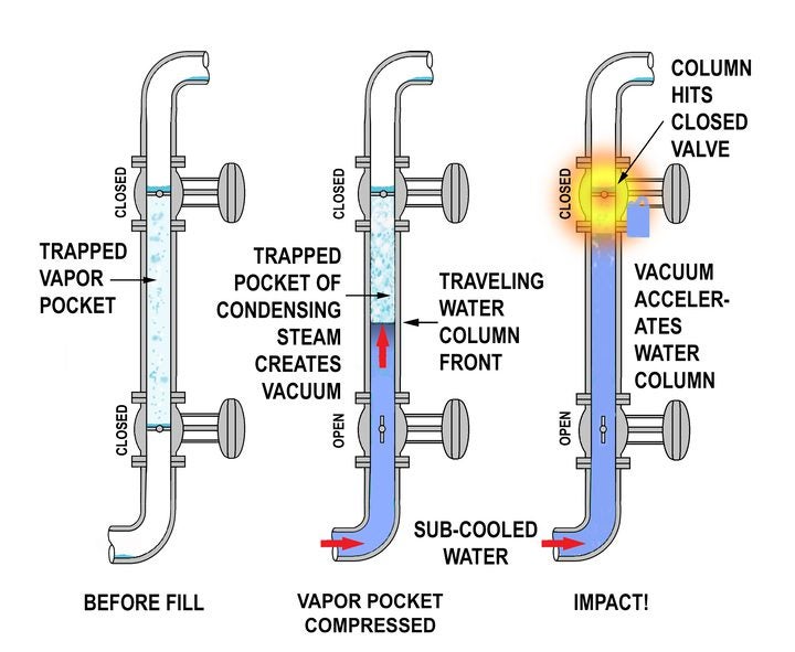
Bottom Filling. When filling the system from the bottom, the water column front will become turbulent as it compresses and condenses the vapor pocket. The pocket will implode, creating a low-pressure zone, which accelerates the water column upward. A large pressure pulse is generated when the water column front strikes the closed steam valve (Figure 4).
To prevent Mechanism 3 transients:
- ■ In a top filling situation, fill the system slowly to promote an annular flow pattern and give the vapor bubbles a chance to escape.
- ■ In a bottom filling situation, install a small bypass around isolation valves, which could be used to slowly pressurize areas where vapor pockets could form.
- ■ Keep the system full to prevent the creation of steam pockets.
- ■ Vent areas where vapor pockets are expected to form prior to system start-up. The air will cushion the blow of a water slug.
Mechanism 4—Hot Water Entering a Lower-Pressure Pipe. Figure 5 shows a pressurized water vessel with a closed discharge pipe. The discharge piping contains stagnant water that will cool over time. When the valve reopens, the sub-cooled water is quickly blown out through the valve without problems. However, when the higher temperature water passes through the valve to the low-pressure side, it will “flash” into steam and the flow will “choke.” When flow chokes, the mass flux (mass flowrate) through the valve is limited. The abrupt change in mass flux from sub-cooled water to hot two-phase flow creates a large velocity change that generates a water hammer shock wave and turbulence at the valve (Figure 5).
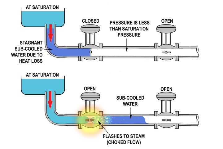
At any point where the water pressure drops below the vapor pressure, the water will flash to steam. Flashing water fills the pipe with vapor bubbles, which can accumulate into a vapor pocket, leading to a water hammer when the vapor suddenly condenses.
Heater drains to the condenser are susceptible to this CIWH Mechanism. Leaky desuperheater spray valves and steam trap failures are typical causes of hot condensate flashing to steam.
To prevent Mechanism 4 transients:
- ■ Install a small bypass around shutoff valves that create cold stagnant pipe legs to get the water moving and prevent a sudden temperature change when the shutoff valve opens.
- ■ Slow the change in the water velocity by slowly opening flow control valves.
- ■ Steam condensate drains piped to a low-pressure condensate collection header should enter through the top of the header. This allows the flash steam to disperse in the steam space and not condense under the liquid surface where vapor bubbles could form, collapse, and create a water hammer.
In addition to condensate and steam interaction events, there are other types and causes of water hammer transients, which are not discussed here. Water slug–induced water hammer occurs when condensate puddles in the pipeline become slugs when steam isolation valves open and the water becomes entrained in the steam. Rapid pump or valve operation will create transients. Water column separation creates a void, which will also result in a water hammer when conditions cause the water columns to rejoin.
These transients can be modeled and analyzed using conventional commercial software for incompressible and compressible flow modeling using the “method of characteristics.” Most water hammer software is not capable of modeling two-phase flow CIWH events. See the EPRI reference mentioned earlier for details. ■
—Michael F. Czyszczewski, PE (mczyszczewski@asme-member.org) is a mechanical engineering consultant with 45 years of design experience in the power industry.