Understanding which valve to use in which application is essential to operate a steam power plant as efficiently and cost-effectively as possible. For example, a critical step in steam power generation is blowdown, the modulation or “throttling” of the flow rate of water flashing to steam. Traditionally, many specifiers and operators of power plants use standard globe valves to achieve this throttling action, but the reality is that standard globe valves are not engineered and manufactured to handle the extreme rigors of throttling.
 |
|
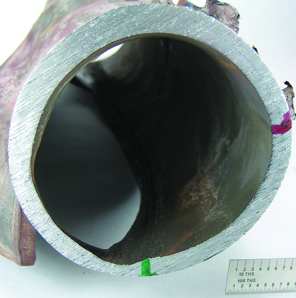
1. Groovy, but not in a good way. Over time, high velocity across the seat makes grooves on standard globe valves called “wire draw,” a term derived because they look like wires. As a result of wire draw, globe valves will not seal when closed, causing leaks. Courtesy: Conval |
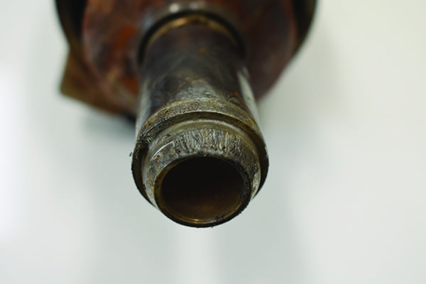
The smaller the gap between the seat and the disc, the faster the wear. Over time, the high velocity across the seat makes grooves called “wire draw,” a term derived because they look like wires (Figure 1). As a result of wire draw, the globe valve will not seal when closed, causing leaks. Taken to an extreme, wire draw can actually eat through the disc like a forked tongue, and cause even more significant damage and flow control problems (Figure 2).
 |
|
2. Problematic. Taken to an extreme, wire draw can actually eat through the disc, causing even more significant damage and flow control problems. Courtesy: Conval |
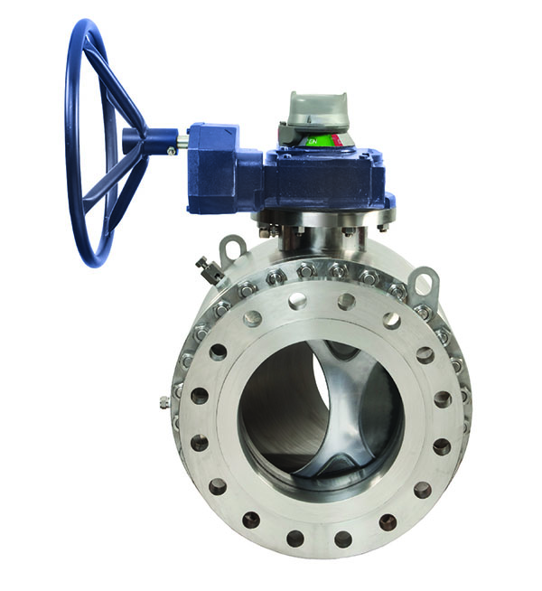
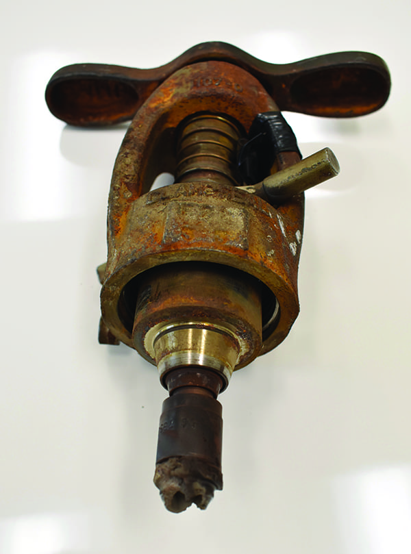
To try to compensate for the limitations of standard globe valves, some plant operators will install two globe valves or a ball valve and a globe valve in-line, one of which provides positive isolation while the other acts as a “sacrificial” throttling valve (Figure 3). However, this approach is an awkward and expensive way to try to achieve throttling with standard globe valves. It is an improvised solution that requires more materials, more welding, more repairs, more replacement, and more expense than necessary.
 |
|
3. Cumbersome and expensive. Installing two globe valves in-line, one of which provides positive isolation while the other acts as a “sacrificial” throttling valve, is an expensive way to try to achieve throttling with standard globe valves. Courtesy: Conval |
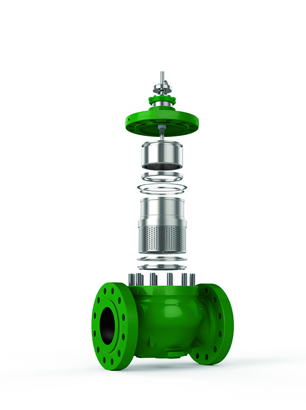
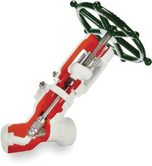
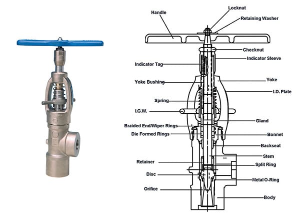
With standard globe valves, if real-life conditions are miscalculated or change, the valve cannot be resized. By contrast, a throttling valve is specifically designed and manufactured to handle the extreme rigors of the throttling process, thereby providing repeatable flow control and dependable shutoff (Figure 4). The unique needle-disc design assures that the pressure boundary is sealed at the smallest diameter possible to ensure maximum sealing capability.
 |
|
4. Inner workings. At left is a Conval high-performance throttling valve. At right is a cutaway diagram of the valve, showing its internal components. Courtesy: Conval |
The orifice is sized to keep fluid velocity across the seat below damaging levels. As a result, the seat is much less likely to wear out; if and when it does, it may be easily replaced. Wire draw is more-effectively eliminated. The stem assembly is mated to the orifice for proper control. The exit orifice angle is designed to minimize downstream piping erosion and noise. If real-life conditions are miscalculated or change, the throttling valve venturi and stem assembly may be resized to match the new condition.
Typically, throttling valves are available in carbon steel SA 105, forged alloy steel SA 182-F22, SA 182-F91 and F92, SA 182-F316, and other materials, in pressure classes from ASME 900 through 4500. Automated throttling valves may be air, motor, or hydraulically actuated.
Recent advances in feed water chemistry further highlight the value-added in-service life with a replaceable venturi orifice resizing option. Generally speaking, if a blowdown valve is being operated less than 30% open, the orifice may be resized for longer valve service life.
The dual-orifice concept and the materials used in construction make the throttling valve nearly indestructible, even in the harshest of conditions. The metering nose of the disc remains in the replaceable orifice-seat cartridge and blocks destructive high-velocity flows until the valve is open enough that the velocities will not damage the seat surface. Hence, throttling valves are increasingly specified and installed in many types of steam power plants, from nuclear to coal and natural gas, including combined cycle heat recovery steam generator plants. In addition to blowdown, some other common applications follow.
Total Dissolved Solids (TDS) Steam Drum Chemistry Control. According to the U.S. Department of Energy Advanced Manufacturing Office Steam Tip Sheet #9, as water evaporates in the boiler steam drum, solids present in the feedwater are left behind. The suspended solids form sludge or sediments in the boiler, which degrades heat transfer. Dissolved solids promote foaming and carryover of boiler water into the steam. To reduce the levels of suspended and total dissolved solids (TDS) to acceptable limits, water is periodically discharged or blown down from the boiler.
Mud or bottom blowdown is usually a manual procedure done for a few seconds on intervals of several hours. It is designed to remove suspended solids that settle out of the boiler water and form a heavy sludge. Surface or skimming blowdown is designed to remove the dissolved solids that concentrate near the liquid surface. Surface blowdown is often a continuous process.
The optimum blowdown rate is determined by various factors including the boiler type, operating pressure, water treatment, and quality of makeup water. Blowdown rates typically range from 4% to 8% of boiler feedwater flow rate, but can be as high as 10% when makeup water has a high solids content. Insufficient blowdown may lead to carryover of boiler water into the steam, or the formation of deposits. Excessive blowdown will waste energy, water, and chemicals. Therefore, having accurate blowdown control is important for efficient plant operation.
 |
|
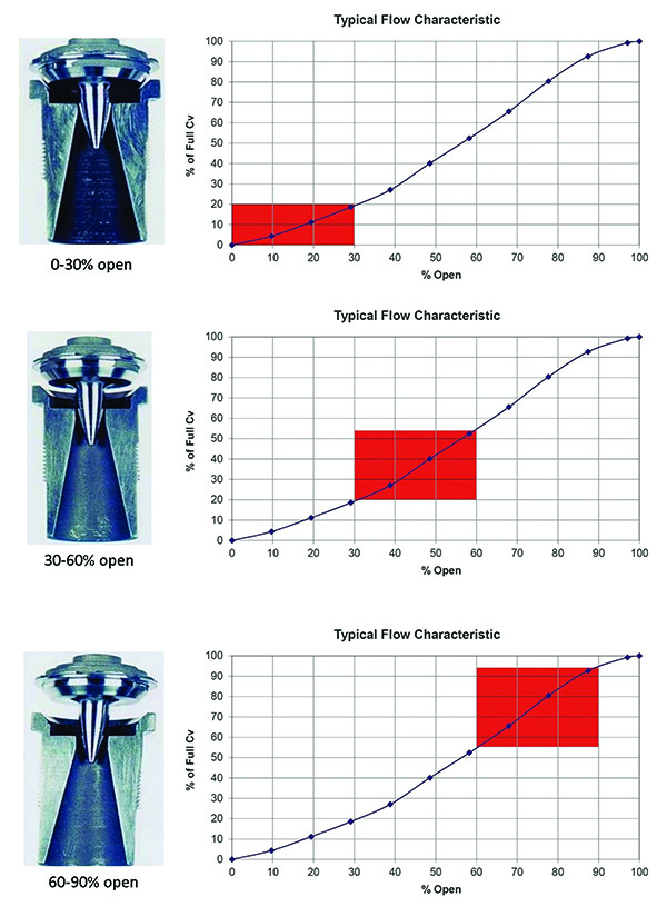
5. Flow curve. The flow curve of a throttling valve is shown here, adjusted for various “valve open” percentages. Cv is the flow coefficient, an important design consideration when sizing and selecting valves for systems; it basically provides a measure of a valve’s capacity based on various system parameters. Courtesy: Conval |
If the flow curve of a throttling valve (Figure 5) is examined, a relatively flat band is noticed in approximately the first 10% of actuation, whether automated or manual. This is the area where the metering nose remains in the orifice and protects the seat from damage. After passing the dead band, the valve allows for linear control of flow and letdown. This design minimizes damage to the sealing surfaces of the valve, so the valve may be closed securely after many cycles.
Wearable or replaceable components are built of very hard materials to prolong the life of these parts. The Stellite 6 alloy used for the disc-nose assembly is rated at a hardness of 50–58 HRc. The hardness of the material provides for a long-lasting surface that is resistant to damage. The seat-orifice-venturi component is made of SS 440C. When annealed, the 440C has a hardness of 60 HRc, which allows the component a very long lifecycle. The venturi maintains location of the vena contracta within the valve, so recovery takes place in the valve while protecting the integrity of downstream piping.
 |
|
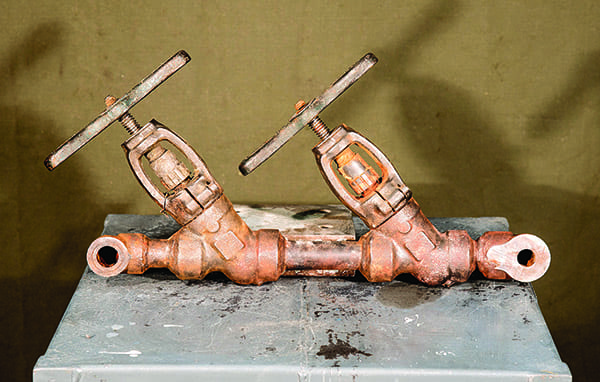
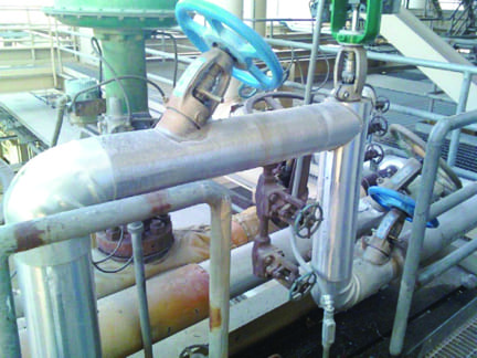
6. Crossover. Two throttling valves serve as a crossover between two steam drums. Operated with controlled actuators, the system bleeds steam from the operating drum to the drum coming up to pre-heat drum surfaces and contents. This allows the power plant to start-up the second drum much faster, saving time and money. Courtesy: Conval |
Quick Start Warm-Up. In Figure 6, two throttling valves serve as a crossover between two steam drums. Operated with controlled actuators, the system bleeds steam from the operating drum to the drum coming up to pre-heat drum surfaces and contents. This allows the power plant to start up the second drum much faster, saving time and money.
Feedwater Bypass. Throttling valves extend the life of cage trim in feedwater regulator valves. Normally, the cage trim would be exposed to high-velocity feedwater during the initial 0–20% opening of the valve, which damages expensive trim components. By contrast, the throttling valve is set up to bypass these damaging flows until load demand is high enough to switch over to the regulator valve when it is open enough not to be exposed to damaging velocities.
Seat Drains. Actuated throttling valves used as above/below main steam seat drains provide reliable service in very harsh conditions. In one instance, the conditions of 3,650 psig at 1,007F destroyed previous valves within a two-year outage schedule. However, throttling valves have lasted for more than 20 years, and are maintained at every outage, which is now conducted on a three-year cycle. Preventive maintenance includes replacement of the disc-nose assembly and seat-orifice-venturi. The longevity of the throttling valves may be extended by integrating a Whisperjet assembly at the outlet of the valve. This modification extends the life of the valve trim and helps to prevent any damage to piping.
Effluent Sampling Valves. Another application for the throttling valve is on hydro-cracker effluent sample stations. The sampling valve is made of SS347 with a SS316 yoke. Other non-standard materials include Ultimet for seat-orifice-venturi and disc-nose. The stem and bonnet are built of Nitronic 50 and the backseat is made with Nitronic 60.
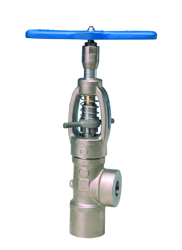
Sight Gauge Isolation. Typically, angle pattern valves are used, but they are often damaged by throttling steam or fluid into a tube or other device, causing leakage and making it difficult to monitor levels. Throttling valves are a superior alternative for this application.
When assessing if a throttling valve is appropriate for your application, keep in mind that a throttling valve is a choke device providing precise control at specific temperature and pressure conditions. A throttling valve is not a control valve in the sense that it does not control downstream pressure. For most blowdown and many other applications, throttling valves are a smart option to consider. ■
—Michael Glavin is vice president of Engineering; Glen Guernsey is South Central Regional Manager; Michael Hendrick is vice president of Global Sales and Marketing; Scott Hilke is Western Regional Manager; and Jeremiah O’Callaghan is a senior engineer with Conval, a manufacturer of severe service valves based in Enfield, Connecticut.