One of the big drivers of the utility industry’s recovery has to be the estimated $15 billion engineered equipment market for flue gas desulfurization (FGD) systems. The Clean Air Interstate Rule (CAIR) has pushed utilities in 28 eastern states and the District of Columbia to retrofit many power plants with scrubbers over the next few years in order to reduce SO2 emissions by an estimated 4.3 million tons by 2010, which is 45% lower than 2003 levels, according to the EPA. At full implementation, CAIR will reduce power plant SO2 emissions in affected states to just 2.5 million tons—73% below 2003 emissions levels.
Scrubber system construction costs have come down from an average over $200/kW since the first FGD push in the mid-1990s to comply with the Clean Air Act Amendments of 1990. Purchase a system today, and the basic FGD system will have a sticker of around $150 to $200/kW, although special site requirements could drive that cost up, sometimes significantly. EPA studies related to CAIR implementation note that the market for FGD systems is on the order of 160,000 MW, requiring an investment of $25 billion. Many industry observers see those estimates as high, with real demand on the order to 80,000 to 90,000 MW. The differences seem to be related to the number of plants that will be retired rather than retrofitted.
Macroeconomic market issues are interesting, but they aren’t very helpful when your plant is under the gun to install an FGD system. Once the decision is made to go ahead with one, it falls to plant engineers to select the right technology from a wide number of options that will match your particular fuel and plant configuration. Visit similar plants and talk to your colleagues. Read the technical literature. Quiz your consultants. In short, do your homework and pay attention to the design details.
Common materials problems
One particular problem reported by engineers during several FGD installations is how to correctly install and clean those stainless steel and nickel alloy components that carry the scrubber slurry and other system fluids. It seems like an inconsequential issue, but field experience has proven otherwise.
Stainless steels and nickel alloys usually are received in clean, uncontaminated condition, but during fabrication, contaminants such as dirt, oil and grease, and embedded iron can be deposited on the metal surface. Dirt can be easily removed by washing with a detergent followed by a water rinse. Oil and grease should be removed because they may contain sulfur, phosphorus, or other elements that could embrittle the alloys if they are subjected to the heat of welding. Degreasing solvents are used for removal of these contaminants.
During handling and fabrication, iron can be embedded in the metal surface. Embedded iron on the surface of the stainless steel can create initiation sites for pitting or crevice corrosion, with the corrosion continuing into the stainless steel beyond the initiation site. However, nickel alloys with over 8% molybdenum do not seem to be affected by embedded iron.
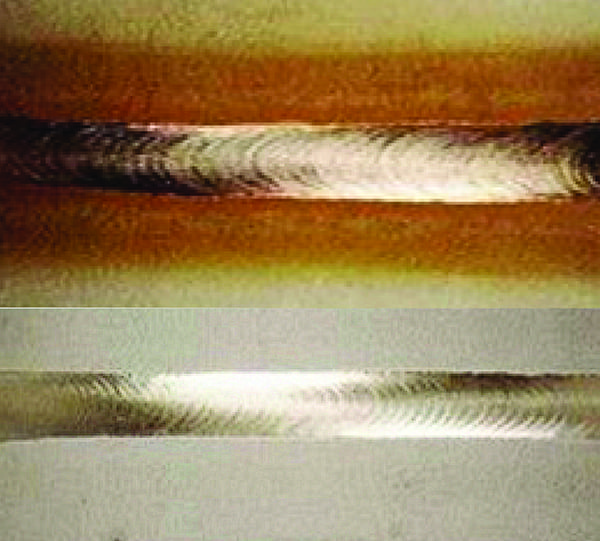
Heat tint has been found to lead to reduced corrosion resistance of stainless steels both in the heat-affected zone and the weld metal. On the other hand, numerous tests have shown that heat tint does not have any significant influence on the corrosion resistance of nickel alloys such as Alloy C-276.
Weld spatter and mechanical defects can also be focal points for pitting and crevice corrosion on both stainless steels and nickel alloys. They should be removed by light grinding with a flapper wheel, but care must be taken to ensure that where sheet linings or clad plate are concerned, grinding does not significantly reduce the thickness of the already-thin sections.
Prefabrication inspection
It is convenient to consider two phases of inspection: inspection of the starting material prior to fabrication and inspection of the finished component after fabrication. Because much of the air pollution control equipment construction may take place at the utility site, the owner should verify that good quality control practices are in place for maintaining product and material identification and ensuring proper storage and handling.
An alloy identification system should be in place, preferably one that will maintain product heat identity so that the product can be traced to a particular mill heat. The identity of the marking method should be one that does not damage the product mechanically or contain compounds that could cause welding defects or contribute to in-service corrosion.
There must be assurances that fabrication procedures are employed that guard against embedding free iron in the metal surface during storage, handling, and fabrication. Typically, iron is embedded by the use of iron or steel tools and handling fixtures or by using iron-contaminated abrasive products such as grinding wheels or disks. Any carbon-steel rack surface that could touch the alloy surfaces should be covered with wood, plastic, stainless steel or other protective materials to prevent the embedding of free iron. Roll-bonded clad plates should be handled and stored in such a way that the carbon-steel backing of one plate does not contact the alloy side of another clad plate.
Prior to welding, all oil, grease, dirt, and other foreign substances should be removed at least 2 inches back from the weld joint area. Similar types of contaminants should be removed from all process-side surfaces prior to placing the material in service to avoid reduced corrosion resistance.
Postfabrication inspection
Postfabrication inspection should confirm compliance with all applicable drawings and specifications. All process-side surfaces should be visually inspected for handling, erection, and/or contamination damage. The thickness of the alloy used for sheet lining or for clad plate is usually as thin as l/16 inch, so damage marks can be a concern. Typically, they are repaired when the damage is 10% of the alloy thickness or 0.010 inch, whichever is less.
In areas where there may be high flue gas flow rates—such as in the absorber or duct-work—the surfaces should be as smooth as practical and free of protrusions or high-weld bead contours. Such irregularities contribute to the buildup of deposits as shown in Figure 1, with the buildup area being around a high-profile weld. Deposits are undesirable because they can contribute to crevice corrosion where chlorides or fluorides can concentrate.
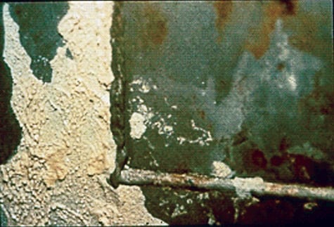
1. Attachment anxiety. Buildup of deposits downstream of a high-profile weld. Courtesy: Richard Avery
Inspecting welds
All process-side welds should be visually inspected to the agreed-upon acceptance criteria and cleanliness requirements. The usual practice is that solid alloy and roll-bonded clad welds are only visually inspected, and additional nondestructive examinations are optional. Liquid penetrant inspection may be used on any process-side weld, including sheet lining welds, to examine questionable areas or when the sheet lining welds are not accessible for leak testing. Liquid penetrant inspection should be performed in accordance with recognized standards such as ASME Boiler and Pressure Vessel Code, Section V, Article 6 or other acceptable codes. The acceptance criteria should be agreed upon by the involved parties.
It is essential that the sheet lining welds be leak-tight to prevent corrosive solutions from reaching the steel substrate. The leak test most widely used on sheet lining welds is the vacuum box test performed in accordance with ASME Boiler and Pressure Vessel Code, Section V, Article 10. Figure 2 shows a vacuum box used to inspect FGD sheet lining welds. A gauge pressure of 10 psi is a widely used maximum value, but it is good practice to start with a lower pressure to first detect any large leaks.
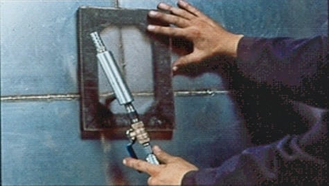
2. Inspect, don’t expect. Vacuum box used to inspect FGD sheet lining welds. Courtesy: Richard Avery
Acceptance criteria
Two industry standards with widely accepted criteria are NACE Standard RP0199, Installation of Stainless Steel Chromium-Nickel Steel and Nickel-Alloy Roll-Bonded and Explosion-Bonded Clad Plate in Air Pollution Control Equipment and NACE Standard RP0292, Installation of Thin Metallic Wallpaper Lining in Air Pollution Control and Other Process Equipment. Their criteria are summarized here:
- All butt welds should be full-penetration welds unless otherwise approved.
- All welds should be free from cracks, overlaps, and cold laps.
- Undercut on solid-plate welds should be limited to 0.010 in. for material less than 3/16 in. thick and 1/32 in. for material equal to or greater than 3/16 in. and less than 1 in. thick.
- Undercut on the alloy side of roll-bonded clad plate or sheet lining welds should be limited to 10% of the alloy thickness or 0.010 in., whichever is less.
Weld reinforcement of butt welds should be 0.094 in. maximum.
NACE Standard RP0292 offers two different weld-reinforcement acceptance values for seam welds and capped plug welds. The commonly accepted U.S. value is 0.190 inch maximum; the European value is 1 t (thickness) maximum. The U.S. value is considered by some to be overly generous, and some utilities have required a lower limit.
Pickling and passivation
Pickling treatments to remove heat-tint oxide along with free iron, and chemical passivation treatments to remove free iron and other contaminants, are often used in other industry applications, but the issue is whether they are needed for FGD service. Furthermore, if they’re needed for FGD, which treatment should be used for which alloys? Because these treatments are time-consuming and expensive, and handling of the chemicals can be hazardous, the treatments should be used only when they are clearly justified.
For this discussion, pickling is an acid treatment using nitric-hydrofluoric acid solutions as described in ASTM A380 to remove heat-tint and surface contaminants such as embedded iron. Chemical passivation is usually understood as a cleaning treatment with a mild oxidant such as a nitric acid solution for the purpose of removing free iron or certain other foreign materials and ensuring the development of a protective passive film. However, if the stainless steel has already been cleaned and all contaminants have been removed from the metal surface, a passive film is formed naturally when exposed to the air. The nitric acid treatment serves mainly as a cleaning step and is not effective in removing heat tint or oxide scale.
A nitric acid passivation treatment is not necessary with the nickel alloys because their superior corrosion resistance results in automatic, natural passivation on exposure to air. Also, their corrosion resistance is not significantly reduced by heat tint or embedded iron.
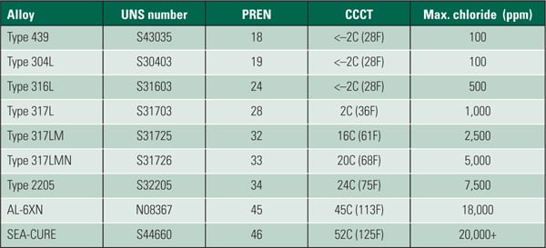
The effect of surface iron in simulated FGD environments has been studied for three alloys: Type 316 stainless steel, a 6% Mo stainless steel, and NiCrMo Alloy C-22. Test conditions were a wet, gaseous, acid-chloride environment using test specimens that were intentionally embedded with iron particles. In the severe test conditions, all Type 316 stainless-steel samples pitted, with iron contamination being particularly detrimental to corrosion resistance. Corrosion of the 6% Mo stainless steel was accelerated by the presence of iron on the surface, but to a lesser extent than observed on Type 316 stainless steel. The presence of iron on the surface of Alloy C-22 did not lead to pitting corrosion, and it was concluded that it was not necessary to remove iron particles for FGD service.
The effect of heat tint on six alloys ranging in alloy content from Type 317 LMN stainless steel to Alloy C-276 in seven highly aggressive acid and simulated scrubber environments also has been studied. The corrosion was measured by weight loss and visual examination for pitting. There was no consistent trend indicating that heat tint caused localized corrosion in the environments with the laboratory test procedures used. There were some indications of localized attack on Alloy 904L in the heat tint area but no indication of reduced corrosion resistance of Alloy C-276 resulting from the presence of heat tint.
For stainless steels, including the 6% Mo grades, it is indicated that heat tint and iron contamination on the surface may lead to pitting and crevice corrosion, and acid cleaning with a nitric-hydrofluoric acid mixture is the preferred method for removing both. The need for acid cleaning should be agreed to by all involved parties. However, for the nickel alloys of the C-family, acid cleaning for the removal of heat tint or surface contamination is neither necessary nor recommended. Passivation treatments also are not required for these alloys.
Lessons learned
Proper inspection and cleaning practices help to maximize the corrosion resistance of stainless steels and nickel alloys in FGD systems. Pay close attention to the following issues.
Know your materials. The need for pickling or passivation treatments varies depending upon the alloy. The presence of heat tint and iron contamination on the surface of stainless steels can reduce corrosion resistance, whereas with NiCrMo alloys, neither the removal of heat tint nor embedded iron is normally considered necessary.
Conduct good housekeeping. Prior to and during fabrication, materials should be properly identified, stored, and maintained free of contaminants that could affect weld quality and in-service performance.
Meet the criteria. Weld acceptance criteria should include full-penetration butt welds; welds free from cracks, overlaps, and cold laps; and meeting agreed-upon acceptance standards for undercut and weld reinforcement.
—Richard E. Avery and William L. Mathay are consultants to the Nickel Institute (www.nickelinstitute.org). Avery can be reached at 603-434-2625 or richardea@aol.com. Mathay can be reached at wlmathay@adelphia.net.