INSTRUMENTATION
Level measurement in harsh environment
A demanding level measurement application in an extreme environment best describes the conditions that Advance Engineer Rick Mezan faced at FirstEnergy Corp.’s 2,360-MW Bruce Mansfield Power Station in Shippingport, Pa.
Required to scrub the exhaust of Bruce Mansfield’s three coal-fired supercritical boilers, plant staff built in 1998 five forced-oxidation gypsum (FOG) columns to turn the output of the scrubbers into commercial-grade gypsum for a drywall factory next door. "We use a lime slurry to convert the sulfites and sulfates," Mezan explained. "The slurry goes into a thickener and settles out. Then we pump the solids into the FOG plant, where the environment is hot, turbulent, and corrosive."
Fog of war
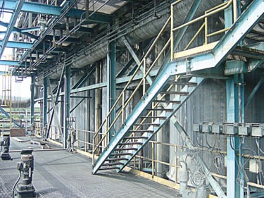
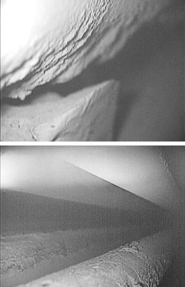
Measuring the slurry level in the five FOG columns (Figure 1) had been rendered impossible by the extreme environment. "The readings we need don’t have to be very precise—between 6 inches and 1 foot," said Mezan. "Manual monitoring was out of the question due to the steam and roiling material inside the columns."
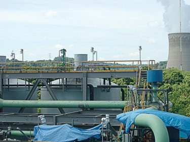
1. Slurry up. FirstEnergy Corp.’s Bruce Mansfield plant uses forced-oxidation columns to convert the calcium-sulfite waste of its SO2 scrubbers into gypsum, the essential ingredient of wallboard. Courtesy: SOR Inc.
FirstEnergy had attempted automated level measurement a few years earlier by installing stainless steel units using radar frequencies. "The highly corrosive slurry simply ate them up within a year," Mezan recalled. "When we pulled them out, they looked like Swiss Cheese. We knew we needed a level measurement system that could handle a very tough environment." Mezan then heard about echOsonix sonic/ultrasonic level sensors from SOR Inc. (Lenexa, Kan.).
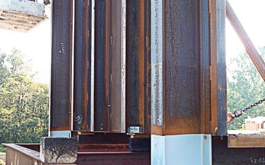
Mike Minteer of Advance Instruments Inc. in Canonsburg, Pa., suggested replacing the radar units with echOsonix units. By now, Mezan was skeptical that anything would perform in the extreme conditions, but he took Minteer’s word that the SOR units, which are made of polypropylene and are Teflon-faced, could withstand the rigors of the harsh environment (Figure 2).
2. Severe service system. The extreme environment within the oxidation columns made level measurement problematic. Courtesy: SOR Inc.
Minteer and SOR Business Manager Kamal Khan arrived in Shippingport in June 2005 to install a single 10-kHz unit. Before the day was out, FirstEnergy had purchased four additional units for the remaining oxidation columns plus two more for the plant’s lime powder silos.
Khan recalled a big surprise he got during installation of the units: "We discovered that the tops of the columns had been extended 10 feet by a fiberglass tube containing a baffle structure resembling an egg crate," he said. "As a result, any level sensor would be challenged not only by dense steam and condensate but also by the constant turbulence the baffles create. Guaranteeing accurate readings both below and above the baffles could have been problematic. However, the high-power, low-frequency, and adaptive-gain features of the echOsonix units enabled us to quickly dial in the proper settings."
Satisfied customer
After six months on the job, the echOsonix units were still producing accurate readings. Mezan is delighted: "We’re currently in process of doubling the number of oxidation columns we use. We plan to install echOsonix transmitters in the five new ones as well."
There are three echOsonix models whose operating frequencies range from 5 kHz to 30 kHz. All use sound waves to penetrate fluids such as steam and foam, which block higher frequencies. This is the same principle that makes foghorns effective. To ensure that echoes bouncing off the surface of targets are strong enough to be detected by a sensor element coated with condensate or deposits, the pulse sent out by the echOsonix’s transmitter section can be made as loud as a heavy-metal concert: 138 dB.
As mentioned, echOsonix units have an adaptive-gain feature. When process conditions weaken return signals, the gain of the receiver section is automatically increased until signals can be read reliably. Once conditions return to normal, the sensitivity is automatically reset to its previous level to avoid reading false echoes. Finally, the low-frequency feature of the echOsonix units enables them to be placed as much as 260 feet above the echo-producing surface.
—Contributed by Russ Carlson, level products manager for SOR Inc. He can be reached at rcarlson@sorinc.com.
ENERGY CONSERVATION
Designing insulation for structures
Much money is wasted by failing to account for the substantial impact of internal pressure and flue/duct plate stiffener geometry on the design and installation of insulation and lagging.
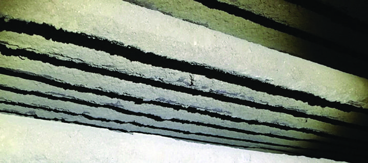
In fact, the size, shape, and arrangement of stiffeners (Figure 3) are the first things to consider when designing insulation and lagging for a new boiler or selective catalytic or noncatalytic reduction (SCR or SNCR) system. Stiffener sizes have changed over the years. Because stiffeners of the past were designed for a much lower water gauge pressure, they were small enough to allow insulation to be placed between them without having to be cut to fit. Today’s stiffeners are much larger and much farther apart for two reasons: higher internal pressures and the failure of design calculations to account for the insulation thickness required by the application.
3. Insulation challenged. Close-up of W8 and W14 external stiffeners. Courtesy: BRIL Inc.
Over time, boilers and air-pollution control systems and their flues and ducts have actually become harder to insulate and lag effectively. There are several reasons for that. One is the length of today’s typical stiffener (greater than 7 inches). Another is that modern equipment tends to run hotter. When consistently exposed to temperatures above 400F, the binder within mineral wool-type insulation becomes prone to burnout. Maintaining the integrity of the insulation in the face of equipment vibration requires supporting it at both the bottom and top. A third factor is business-related. It has become standard practice among original equipment manufacturers of boilers and SCR and SNCR systems to subcontract the job of insulating and lagging their gear to the lowest bidder. The cheaper the system, the shorter its life expectancy.
In addition to the duct pressure and temperatures that the insulation/lagging system is designed for, the arrangement of stiffeners depends on flue and duct design as well as stiffener sizing and spacing. Designing the flue or duct arrangement or the casing for an SCR or SNCR box is no easy task. The three key factors that affect insulation and lagging design are space constraints, gas temperature, and internal pressure. In the author’s opinion, internal pressure is the most important but the least understood.
Stiffeners are essentially sized for a particular span, pressure, and temperature. However, expected stresses and deflection may impose their own limits. As a result, it is best to wait until the flue or duct system has been laid out before structurally designing the individual components of its insulation/lagging system (including stiffeners) to withstand the following forces:
- The internal static pressure of the contained fluid (in this case spent gas or air).
- The transient pressure specified for the system.
- The dead weight of plate, stiffeners, insulation, lagging, etc.
- Wind and seismic loading.
- The actuation forces of expansion joints.
- Ash accumulation (if applicable).
- Loads transferred from other equipment.
Taking this approach, design engineers can determine stiffener size and spacing from steel stress design formulas in the Manual of Steel Construction of the American Institute of Steel (www.aisc.org). The two variables in the formulas that directly affect insulation and lagging system design are stiffener spacing and internal pressure. The higher the internal pressure of a structure, the larger its stiffeners must be (Figure 4).

4. Major cover-up. Insulation humped over large stiffeners. Courtesy: BRIL Inc.
Leading-edge lagging
It is quite common to find stiffeners of 12 inches or longer on the hot flues and ducts or casing of SCR and SCNR systems operating at 600F or higher (Figure 5). For such applications, it is economically impractical to hump or bury the stiffeners, so the only option is to insulate their exterior surfaces. One way to support the insulation is to weld it to the stiffeners with a 22-gauge inner support plug. This approach also allows the use of insulation systems such as H-bars and preinsulated lagging panels, which, in the past, never would have been found on systems operating at more than 450F.
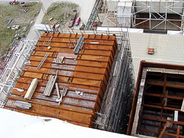
5. Ready to insulate. The top of a typical selective catalytic reduction system equipped with 12-inch stiffeners. Courtesy: BRIL Inc.
Three of today’s most commonly used systems for attaching lagging to large stiffeners are the H-bar system, preinsulated lagging panels, and inner support systems.
The H-bar system. This pefabricated and preengineered system is designed and fabricated off site and then installed at the job site or at the flue fabricator’s shop. It was originally designed to be used on low-temperature applications (450F and below). The system, which is fabricated in much the same way as are continuous gutters, is installed over the outside of the stiffeners. The H-shaped steel channels (two C-channels back to back) are attached to the external surface of the stiffeners, forming a "picture frame" in which the insulation can sit. The height of the H-bar should match the thickness of the insulation. Lagging is then attached directly to the H-bar frame.
Preinsulated lagging panels. This system is a prefabricated and preengineered system that is designed, fabricated, and installed at the job site or off-site. The panels themselves are fabricated from aluminum lagging laid face-down on a shop table. After welding pins to the lagging sheet about 12 inches apart, the insulation material is impaled on them and covered with aluminum foil and a galvanized mesh (generally, a piece of 16-gauge material measuring 2 x 25/8 inches). The mesh keeps the insulation in place and helps keep the fibers from settling to the bottom. To hold the panel together, a 2.5-inch square speed clip is placed on the pins, which are then bent over. The panel then can be attached to the outside of the stiffeners either directly or via a subsystem of angle iron.
Inner support systems. These systems are placed over the top of external stiffeners to support the insulation and lagging. One way to attach the system is to install 22-gauge lagging material and plug-weld the lagging to the stiffeners before installing the insulation and external lagging. The advantage of this system is that it places the external lagging in direct contact with the insulation, creating support for it on top and bottom. The insulation and lagging are attached to the inner support system by a separate arrangement of pins, clips, Z-clips, and/or sub-girt. Another way to attach the inner support system is to use a 6-inch square road mesh or expanded metal in lieu of the 22-gauge inner lagging. However, because mesh or expanded metal has open areas, this attachment method leaves the insulation’s binder vulnerable to burnout and the insulation itself vulnerable to vibrating away.
The right design
Insulating and lagging boiler or air pollution control systems and their flues and ducts often aren’t considered high-profile tasks by designers and installers. But they should be, because both are critically important and require careful consideration. For example, insulating a pollution control system with a high water gauge usually requires using more than one of the techniques described earlier.
Insulation and lagging systems should be chosen carefully because they have very specific thermal expansion, material handling, and clearance issues that must be addressed during the design stage. Consider the following design and installation criteria when specifying your insulation:
- All external stiffeners used on the same rectangular surface should be the same height—a height that meets span requirements.
- Whenever possible, the height of stiffeners should be limited to 7 inches and be no greater than the minimum insulation thickness, plus 2 inches.
- For economic reasons, stiffeners should be spaced 24, 36, or 48 inches apart wherever possible to allow for the use of standard-width insulation.
- When the specified insulation thickness is within 2 inches of stiffener height, the thickness should be increased so stiffeners can be buried at least 0.5-inch deep.
- If external stiffeners are spaced 6 feet or more apart, it’s best to hump insulation over them.
A final recommendation for insulating "hot" systems completes this discussion. When the height of external stiffeners is greater than 7 inches, a 22-gauge inner lagging should be installed over their tops to support the insulation. If the height of the stiffeners is 7 inches or less, two layers of 4-inch-thick insulation are sufficient to bury the stiffeners. In addition to reducing labor and materials costs, this approach produces the following benefits:
- Support of the insulation both at the top and bottom (assuming the lagging is placed in direct contact with it).
- Elimination of potential heat transfer between the stiffener and the surface of the lagging.
- Fewer thermal expansion issues, because the expansion is absorbed by the insulation attachments (pins) and lagging support system (Z-clips, studs, sub-girt). This attachment approach presents fewer expansion challenges than a structurally supported system such as the H-bar or preinsulated lagging panels.
- Minimized clearance difficulties.
- Elimination of binder burnout, because the insulation is sandwiched between the flue plate and the outer lagging.
—Contributed by Gary Bases, author of The Bril Book (a complete guide to brick, refractory, insulation, and lagging systems) and president of BRIL Inc., an independent consulting firm. He can be reached at 330-665-2931 or brilinc@adelphia.net.
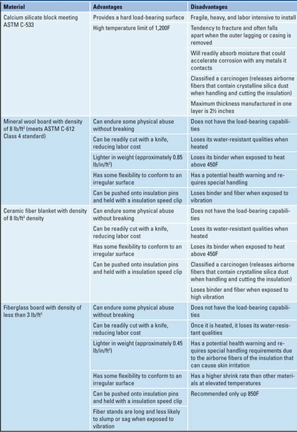
BOILER MAINTENANCE
Shockingly clean boiler
A primary concern of operators of coal-fired boilers—particularly those firing coal with high fouling tendencies—is how to effectively and efficiently clean ash deposits from heat exchanger surfaces. Conventional sootblowers can be problematic because they have complex moving parts, do not clean adequately in areas outside the jet’s line of sight, consume valuable steam or compressed air, and can increase tube wear by entraining ash particles at high velocity during operation.
Pratt & Whitney has long been an industry leader in the development of pulse detonation propulsion technology for applications including commercial and military aircraft, missiles, and rockets. Leveraging this expertise, Pratt & Whitney has developed an on-line detonation cleaning product, aptly called the ShockSystem (Figure 6).
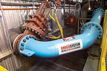
6. It’s a blast. Typical installation of the ShockSystem. Courtesy: Pratt & Whitney
Pulse detonation creates a controlled gaseous explosion in a combustor outside the boiler. The blast wave produced propagates in all directions inside the boiler, even around obstructions, reaching areas that are not in the external combustor’s line of sight. Because the detonation is a separate combustion process, it does not require boiler steam or high-pressure plant air. Because the blast wave, which accelerates entrained ash particles to a relatively low velocity, has a short duration, it is expected to produce less wear on boiler tubes than conventional sootblowing technology.
Cure worse than the disease?
Industry data suggest that about one in every seven tube leaks in coal-fired utility boilers may be attributable to sootblower erosion. A large body of research specific to coal-fired boilers indicates that impacting particles such as flyash remove protective oxide layers as well as metal from tube surfaces. This not only directly erodes tube metal but also leaves it vulnerable to corrosion from flue gas. The research suggests that particle velocity is a primary factor in the process: The higher the velocity, the greater the erosion and potential for corrosion.
Boiler tube erosion and corrosion are synergistic. The rate of metal removal reaches a maximum when both mechanisms occur simultaneously. As a result of repetitive impacts by flyash entrained in flue gas or a sootblower jet, a boiler tube’s protective oxide layer can be reduced in thickness or removed entirely, depending upon the severity of the erosion. The reduction or elimination of protection increases the diffusion rate of corrosive elements through the oxide layer, resulting in a time-average corrosion rate that is much higher than that for normal flue gas.
Even accounting for differences in coal properties and boiler settings, the rate of tube erosion has been found to correlate with the cube of the impact velocity of flyash. In other words, doubling the particle velocity increases the erosion rate eightfold. Designers of pulverized coal–fired boilers usually limit the normal flue gas velocity in the boiler’s convective pass to 50 to 60 ft/sec to limit the tube metal removal rate associated with flyash erosion within 3 to 4 millionths of an inch per hour.
Particle velocities and dwell times for three potential sources of boiler tube erosion. Source: Pratt & Whitney
Lance a lot
The expanding jet from a sootblower lance mixes with roughly an equal volume of flue gas for every jet diameter it travels. Thus, by the time the jet reaches the tubes, it consists largely of ash-laden flue gas. Although there are variations in nozzle geometry and range, sootblowing media, and source pressure to account for, it is reasonable to estimate that the jet’s impact velocity at the tube surface is about 1,400 to 2,900 ft/sec, with the jet impact’s dwell time on a given tube on the order of tens of milliseconds. That impact velocity is, on average, forty times the normal flue-gas-imparted impact velocity.
A system capable of decreasing the jet impact velocity and dwell time would certainly reduce tube surface erosion. Those are the two salient characteristics of the ShockSystem. The velocity imparted to flyash by the ShockSystem blast wave is significantly lower because the peak gas velocity following the blast wave is estimated to be in 170 to 900 ft/sec range, with an effective dwell time of about 1.5 milliseconds on a given boiler tube. The table compares the particle velocities and dwell times of flyash in flue gas, gas accelerated by the ShockSystem, and a conventional sootblower jet.
The ShockSystem produces a highly turbulent "blowdown" jet that maintains a velocity in excess of 3,000 ft/sec for several feet from the nozzle. This jet usually is directed away from boiler tubes to avoid eroding them. However, in some situations the blowdown jet is used to facilitate removal of tough deposits. In such cases, conventional tube shield protection measures should be employed locally to minimize adverse effects.
So far, so good
Initial uses of the ShockSystem on the lower backpass of utility boilers confirm that the blast wave removes platenization (back-spacing) and gas lane pluggage while not removing or eroding away the more tenacious ash sublayer from boiler tube surfaces (Figure 7). If the ash sublayer is not removed, neither is the underlying protective oxide layer. Accordingly, it is anticipated that the blast wave will make only a negligible contribution to tube wear.
7. Squeaky clean. Economizer platenization at the third and fourth tube rows of a boiler powering a 1,000-MW class unit before (top) and after (bottom) deposit removal by a ShockSystem. Courtesy: Pratt & Whitney
Long-term ShockSystem erosion data from the field are still being generated. However, an equivalent pulse detonation-based technology has been in continuous use on two 110-MW utility boilers in Bosnia and Herzegovina since the early 1980s. The O&M records at that site substantiate the effectiveness of using blast waves to clean boiler tubes of deposits: The number of tube bursts was 30% lower than conventional sootblowing had produced.
—Contributed by Mark M. Parish of Pratt & Whitney. He can be reached at 425-278-2410 or mark.parish@pw.utc.com.
PREVENTIVE MAINTENANCE
Shockingly clean boiler
Alcoa Inc.—the world’s largest producer of primary and fabricated aluminum—doesn’t like surprises, especially unplanned downtime of a power plant that interrupts production. Like other global leaders, Alcoa continues to grow its bottom line with an aggressive reliability program. But it’s hard to eliminate unplanned downtime without infrared (IR) thermographic surveys of the switchgear of a generating station whose newest unit is 36 years old.
The Warrick Power Plant in Newburgh, Ind. (Figure 8) is a four-unit, 742-MW, coal-fired, steam-electric facility. Alcoa owns Units 1 through 3, which are rated at 144 MW each, and one-half of Unit 4, rated at 300 MW (Vectren Corp., an Indiana gas and electric utility based in Evansville, owns the other half). All four units entered service between 1960 and 1970. Nearly all of the generation that Alcoa owns is used by the company’s Warrick Operations, an integrated smelting and fabricating facility that produces aluminum sheet for beverage and food can ends and tabs, as well as other flat-rolled products.
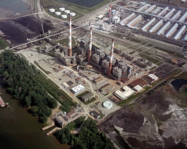
8. Bird’s-eye view. The Warrick Power Plant in Newburgh, Ind. Courtesy: Mikron Infrared Inc.
Old dog, new trick
The days of opening panel doors for those thermographic surveys ended with the plant’s adoption of Alcoa’s Electrical High Voltage Safety Standard 32.60, which is even more stringent than NFPA 70E. But Senior Power Reliability Engineer Brent Welz found an inexpensive and clever workaround: the Viewport from Mikron Infrared Inc. (Oakland, N.J.).
Viewport is a simple 0.50-inch opening that’s UL approved and lacks an IR-transparent window. Like a keyhole, a Viewport allows a thermographer with Mikron’s SpyGlass lens to do IR scans with the doors closed, eliminating the need for "NASA suit" personal protection equipment (Figure 9). The $50 port is significantly less expensive than the $300 to $600 cost of a unit with an IR-transparent windows, the only other alternative for closed-door inspections. "Having installed over 60 Viewports, we figure we’ve saved more than $20,000," said Welz.
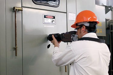
9. Elegant inspection. Capturing an infrared image through the inspection Viewport. Courtesy: Mikron Infrared Inc.
"Our two options for open-door inspection of medium-voltage switchgear under the Alcoa safety standard are to wear 100-calorie protective gear or to operate the IR camera remotely from a safe distance," Welz explained. "The suit imposes physical limits on what a thermographer can do and see while using the IR camera. Need I add that it can get intolerably hot inside that suit as well? Operating the camera remotely eliminates the suit but does make setting up and aiming the camera a bit more difficult."
More energy, lower cost
IR surveys have proven their worth for Alcoa, so Welz first investigated whether units with IR-transparent windows could be used for closed-door inspections of switchgear. Here’s what he found.
IR windows are made of various crystalline materials, all of which reduce to some degree the amount of infrared energy reaching the camera’s detector. The windows used on electrical cabinets typically transmit IR energy only in the wavelength of 0.13 to 10 microns. However, the "sweet spot" of an infrared camera is 8 to 14 microns. If the window cuts off at 10 microns, the camera misses more than 70% of the energy emitted by the target. This reduced energy reaching the detector lowers image quality and severely compromises temperature values computed by camera algorithms established for the 8 to 14 micron range.
"The reduction in IR energy is critical when you’re looking at switchgear," Welz explained. "Switchgear is usually oversized for the load, so it will run cool. As a result, the IR camera must detect subtle temperature differences in an environment with very low levels of emitted infrared to begin with. This makes it difficult to identify what you’re seeing in the camera so you know you’re scanning the correct targets. Anything that attenuates the energy reaching the camera’s detector is going to compromise results."
IR windows present practical issues as well. The windows’ hygroscopic crystal materials absorb moisture over time, reducing image quality. The crystal material also is easily scratched or cracked, so a camera lens barrel cannot be pushed against it. Removing heavy bolt-on switchgear cabinet doors risks breaking the window if the panel flexes or absorbs an impact. And, like any window, an IR window will attract dirt and oils, making cleaning the inside surface difficult.
However, according to Welz, "the greater concern for us was the cost of the windows—$300 to $600 each. Using a camera’s standard lens, you’d need more than one window for each cabinet. With a wide-angle lens, you’d probably need a larger, more expensive window because the wide angle usually has a larger-diameter front optic. We swallowed hard and were planning to try some windows, but then we heard about Mikron Infrared’s Viewport. At $50 for a nonlocking port and $85 for the locking version, changing direction was a no-brainer. The Viewport is part of a system that requires a special wide-angle lens, but it’s one that our thermography service has," he explained.
Simple system
"We currently have about 60 ports installed, and we add more during scheduled outages," Welz said. "With the port and the lens, there’s a defined area you can view at a certain distance, and we position the port to adequately cover the cabinet interior. We’ve been using one port per cabinet. Had we used IR windows, we probably would have needed more than one per cabinet. Standard IR camera lenses don’t have a 54-degree field of view, and they focus to only 12 inches. You can’t press the lens on the window anyway, so when you back the camera away from the door surface, you never get your full field of view inside the cabinet."
Coverage and image quality (Figure 10) are as good today as when thermographic surveys used to require the removal of switchgear cabinet doors, Welz added. "The time saved is substantial, as well. Using Viewport, we can scan all the switchgear of a generating unit in about 45 minutes. That would take 4 to 5 hours if we removed the doors and either worked the camera remotely or used protective equipment."
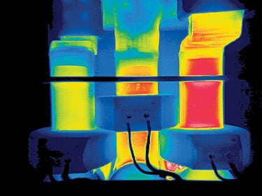
10. Inside look. Image of 4-kV breaker taken with a SpyGlass lens through a Viewport. Courtesy: Mikron Infrared Inc.
In fact, the only protective equipment needed when scanning switchgear through the Viewport is what Alcoa classifies as Level 2: hardhat, safety glasses, ear plugs, and no synthetic fabrics. "It’s a big step down from the 100-calorie suit and makes the job fast and easy," said Welz. "The ports may turn out to be even more valuable once we begin using them on our 480-V equipment. The close quarters in their cabinets has already proven the worth of close-focusing, wide-angle lenses. Finally, we think the Viewports will facilitate our use of ultrasound detection, which we’re currently implementing."
—Contributed by Mikron Infrared. Contact the company at 888-506-3900 or e-mail jon@mikroninfrared.com.