Remember the slogan, "Never trust anyone over thirty?" Chances are you’ve joined the ranks of the over-thirty generation and are dealing with your own personal "maintenance" issues—not unlike the fleet of generators at larger U.S. power plants, whose average age is about 30. Given the continuing growth in U.S. electricity demand and the cost and difficulties of building a new coal-fired plant, it’s safe to conclude that our existing coal-fired fleet will be with us for some time to come. An aging Mickey Mantle quipped, "If I knew I’d live so long, I would have taken better care of myself." Likewise, the utility industry needs to pay closer attention to generator maintenance to ensure the future viability of these "middle-aged" plants.
A significant proportion of the existing U.S. coal-fired fleet has generators whose stators are directly inner-cooled by hydrogen. With three decades of experience operating these generators now under its belt, the industry has identified several fleetwide chronic maintenance problems that can result in extended unplanned outages and significant lost-generation and repair costs. Portland General Electric’s (PGE) Boardman Power Plant has experienced these problems first-hand. But rather than yield to the temptation to make a quick fix, Boardman sought a permanent solution to the nagging problems.
The long road back
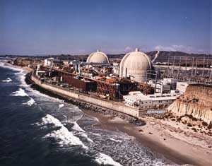
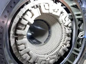
The single-unit, coal-fired Boardman plant, which celebrated its silver anniversary this year, looms over the high desert of eastern Oregon. Westinghouse Electric supplied the frame 2-105 x 245 generator, each of whose stator bars is directly cooled by hydrogen through a single tube stack (Figure 1). The generator has the following nameplate ratings at 60 psig H2:
- Output: 590 MVA
- Stator voltage: 24 kV
- Stator current: 14,193 A
- Rotor current: 4,337 A
- Rotor voltage: 475 V
- Power factor: 0.95

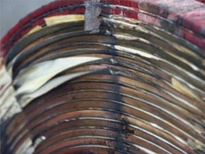
1. Hydrogen flows through the generator non-drive end stator bar cooling tubes. Courtesy: Alstom Power
During the first few years following its commissioning, the Boardman plant was operated on a very limited basis, and it essentially didn’t operate at all between 1986 and 1988. The plant didn’t reach a 40% capacity factor until 1990. But even during those early years, the following generator problems began to become apparent:
- Stress-corrosion cracking of the 18Mn-5Cr retaining rings. This led PGE to regularly inspect the rings to detect cracks before they could propagate to a critical size.
- Rotor top-tooth cracking. Westinghouse said this might be a problem, and PGE’s experience confirmed that it was indeed.
- Loosening of the stator core laminations. This problem was first identified at the Boardman plant by a generator inspection during a 1993 outage. The laminations were not retightened at that time.
- High stator endwinding vibration levels. Throughout the 1980s and 1990s, the unit experienced relatively high endwinding vibrations, on the order of 10 mils. To mitigate the damage the vibration might cause, PGE instituted annual outages for endwinding inspections.
Uprating hits a limit
Beginning in the late 1990s, the changing economics of power generation dictated that PGE run Boardman as a baseload unit. With a shift in operating mode, the utility began to make investments in the plant to maximize its output. PGE first retrofit the low-pressure turbines, increasing the generator’s output to 626 MVA. Then, in the spring of 2004, the utility retrofitted Boardman’s high-pressure turbine, upping the output to 676 MVA. At that point, PGE realized that it made no sense to put more money into uprates before permanently solving the four known generator problems. The solution would be costly, but the payback would be significant—long-term, reliable operation of the plant at a much higher output.
The entire generator overhaul project (with the exception of an upgrade of the excitation control system) was awarded to Alstom Power Inc. (Richmond, Va.). Following are descriptions of the work that Alstom did.
Rewinding the generator rotor. As part of a complete rewind, Alstom installed new class F insulation and 18-18 retaining rings and repaired cracking in the rotor’s tooth tops with a short-ring modification. Westinghouse recommended the use of the class F insulation based on its studies of the effect of uprating on rotor operating temperatures.
The rotor was rewound at Alstom’s Richmond service center. After removing the retaining rings, Alstom performed MT (magnetic particle testing) at the rotor’s tooth tops to check for cracks. The inspection found linear indications of cracking outboard of the snap ring groove at 51 of 72 locations at the drive end (DE), and at 26 of 72 locations at the non-drive end (NDE). Also found were a few indications of cracks inboard of the snap ring groove.
Engineering evaluation of the inspection determined that Alstom’s short-ring modification would remove all of the indications and prevent any future cracking problems. The short-ring mod entailed removal of material susceptible to cracking from each side of the tooth top (Figure 2). The few indications of cracks inboard of the snap ring groove were very shallow and were removed by increasing the radius under the tooth top.

2. Cracked tooth repair. Machining of the tooth tops removed potential crack propagation sites by removing the material susceptible to cracking at the tooth top. The photos shown were taken before (top) and after (bottom) the machining was completed. Courtesy: Alstom Power
The rewind added new, class F Nomex slot liners, NEMA G-11 creepage blocks, and retaining rings. The existing blocking was determined to already be class F insulated and was reused. New 18-18 retaining rings then were machined and installed. Balancing was done with the new slip ring shaft installed to ensure proper balancing of the complete rotating assembly (Figure 3).
3. Rotor prep. The rotor was balanced before the generator was reassembled Courtesy: Alstom Power
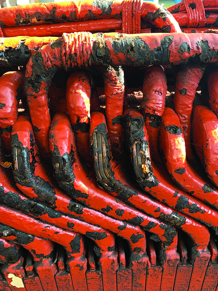
Installing a new static excitation system. The system included a new slip ring shaft, new brush rigging, and a new excitation control system. Alstom supplied the first two pieces and a new steady bearing as well.
One of the project’s requirements was to retain the existing exciter housing. Doing so required modifying it to allow proper air flow for cooling the slip rings and brush rigging, adding inlet and outlet air louvers with filters, and mounting a circulating fan on the slip ring shaft. The new brush rigging features Alstom brush holders that allow the brushes to be inspected or replaced while the generator remains in service.
Retightening the stator core. The original plan for this part of the project was to torque the hex nuts on the ends of the stator’s through bolts and building bolts. But Alstom technicians found that friction between the bolts, hex nuts, and washers made it difficult to precisely control the amount of tension applied. Alstom also was concerned that twisting the bolts might damage their insulation. So the decision was made to replace the hex nuts with hydraulic nuts (Figure 4). Hydraulic nuts were chosen for two reasons: They are easily accessible for future retightening, and the tension on each bolt can be precisely set by controlling the pressure applied to its nut.
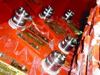
4. Different nuts. Hydraulic nuts replaced hex nuts to enable precise tensioning of the stator’s through bolts and building bolts. Courtesy: Alstom Power
To determine the proper tension for the bolts, Alstom began by setting a nominal value for the interlamination contact pressure, based on company standards. The total force applied to the stator laminations was calculated by multiplying this pressure by the stator core’s cross-sectional area. This total load then was divided by the number of through bolts and building bolts to determine the nominal bolt tension.
The existing through-bolt hex nuts at the stator’s NDE were replaced with hydraulic nuts in groups of four to ensure that the core did not lose compression. After mounting all of the hydraulic nuts, the through bolts were tensioned in three steps, starting at 80% of the final value. A waiting period between the steps allowed the core to settle, ensuring maintenance of final bolt tension levels.
Following replacement of the through-bolt hex nuts with hydraulic nuts, the building-bolt hex nuts at the stator’s DE and NDE were replaced using a similar procedure, but with different tension specs. Because these building bolts are fixed to the frame at the center of the stator, each half of the building bolt tightens half of the core length. After the hydraulic nuts were installed on the bolts at the NDE and DE, they were tightened to 100% of the final value. Final electrical testing of the through bolts, and EL-CID (Electromagnetic Core Imperfection Detection) testing of the stator core revealed no problems.
Designing a new endwinding support system. The new system was intended to minimize endwinding vibrations resulting from plant power uprates and increased MVAR loading. In 1997, PGE studied the problem and concluded that vibration levels would increase to unacceptable levels if the Boardman plant’s output was uprated further.
To solve this problem, PGE asked Alstom to design a new endwinding support system that could do the following:
- Reuse existing windings.
- Uncouple endwinding vibrations from the core.
- Enable retightening.
- Reduce measured end-turn vibration to less than 5 mils, peak to peak.
- Shift overall basket n = 2 vibration modes outside of the 110-Hz to 140-Hz range.
Alstom designed a free-floating support system (Figure 5) that met all of the requirements. The system’s outer support ring incorporates multiple pressing plates equally spaced around the outside of the winding head. These plates press radially on the outside of the winding head through a special, adjustable tightening device. The system’s inner ring supports the interior of the winding head. The pressing plates’ compression of the windings against the inner support ring creates a very cohesive endwinding basket structure that is resistant to vibration.
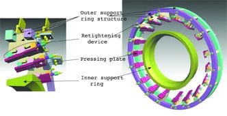
5. Alstom’s free-floating endwinding support system. Embedded in its outer support ring are multiple pressing plates equally spaced around the outside of the winding head. Courtesy: Alstom Power
The inner and outer support rings are made of glass-epoxy and filament-wound rings. All other system components are made of high-strength glass-epoxy laminates. At the NDE, the outer support ring also carries new phase rings, which replace the old frame-mounted phase rings. Alstom has used this retightenable system design with great success since the 1970s.
Preparation for installation of the new support system began with baseline inspections and tests. An initial bump test established the baseline data for endwinding vibration characteristics. The DE of the stator had a 4-node mode at 109 Hz and a cantilever mode at 127 Hz. The NDE had a 4-node mode at 115 Hz and a cantilever mode at 127 Hz. The 4-node modes are of concern because they are readily excitable by the 120-Hz forcing frequency of the machine. A comparison of these baseline results to the results of a final bump test, after the system was cured, was used to verify its effectiveness.
On to assembly
Alstom’s initial inspection of the stator winding found it to be in relatively good condition. Visual inspection of the winding heads detected some areas of "greasing" and partial discharge on both the DE and NDE. There also were some broken ties on spacer blocks. Electrical tests similarly showed the stator windings and insulation to be in generally good condition. A Transposition Voltage Comparison Test detected a broken strand in the bottom coil of slot #35, but PGE determined that it was a manufacturing defect. Finally, a Vent Tubes—Vent Tubes Resistance Test found two "floating" tubes in the bottom bars of slots #2 and #31. These were repaired by installing a new resistor on slot #2 and by re-soldering the resistor connection on slot #31. All other initial testing found no problems with the stator winding that required attention.
Alstom prepared the winding heads for the installation of the new endwinding support system by removing the old support system’s coil support brackets, coil braces, top coil support ring, and (on the NDE) the phase rings and phase ring supports. Inspection of the winding head surfaces found places where the diamond spacers between the bars protruded significantly above the surface. To ensure good contact at the interface between the support system and the winding heads, Alstom ground flush with the surface of the winding head any protruding spacer blocks that might contact the inner support ring or pressing plates.
Assembly of the new endwinding support system began with installation of the inner support rings. Layers of epoxy-impregnated glass and polyester felt were applied to the rings’ outside surface to serve as a conformal layer and provide a good mechanical bond between each ring and the surface of the windings. The outer support ring structure then was assembled in place and centered on the winding head. With temporary tooling holding the ring structure in place, the tightening devices were assembled between the support plates and the winding heads. Layers of glass and polyester also were applied between the pressing plate and outside of the winding head.
The final step of the assembly process was to install the phase rings at the NDE of the stator by securing them to the brackets (Figure 6). Connections then were made to the existing phase bars by means of parallel copper plates brazed to either side of the phase ring ends and soldered to the phase bar strands.
6. Holding on. Brackets for mounting the phase rings were installed on the outside of the outer support ring structure. Courtesy: Alstom Power
With the assembly complete, the next step was to heat-cure all of the epoxy in the support system. As part of this process, it was critical to maintain constant pressure on the winding head. This was accomplished by means of special tooling installed against the inner support rings and on the retightening devices.
Bump testing was performed after the heat curing was complete. The NDE results were very good, indicating no excitable vibration modes within the 110-Hz to 140-Hz range (Figure 7). Several 6-node modes did show peaks in this range, but they did not cause concern because they are not easily excited by the 120-Hz forcing frequency of the machine.

7. Final non-drive end bump test results for the new support system. Shown is the basket average response at the outer ring. Courtesy: Alstom Power
Passing final exams
After the successful completion of final electrical tests on the support system, the Boardman plant’s generator was reassembled. The plant then was brought back on-line and closely monitored for any operational problems. No significant problems were detected.
More importantly, data provided by the endwinding vibration monitoring system indicated dramatic reductions in endwinding vibration levels. Data taken before Boardman was shut down indicated a peak vibration level on the end windings of the DE of approximately 10 mils, with the generator loaded at 541 MW. Post-overhaul readings indicated that with the generator loaded at 628 MW, the peak vibration levels at its non-drive and drive ends were 2.4 mils and 1.4 mils, respectively.