Over the past decade, since industry deregulation, the typical utility power plant has lengthened the maintenance intervals of its major systems to minimize downtime and costs. Many plants schedule spring and fall outages based on the inspection and maintenance needs of turbines. In the process of juggling maintenance activities and scarce dollars, generators and exciters may get less attention than prime movers. Consider the following "baker’s dozen" list of typical failures when developing your checklist for maintaining generators and exciters.
Migrating rotor turn insulation
Problem. Across the industry, a number of generator rotors have experienced the problem of turn insulation migration. The insulation between the copper turns slips out of position because the adhesive bond between the insulation and the copper breaks down. Short-circuits develop as bare copper is exposed. Coils with shorted turns run cooler, and this causes a temperature imbalance. If enough turns develop shorts, rotor vibration can increase to unacceptable levels.
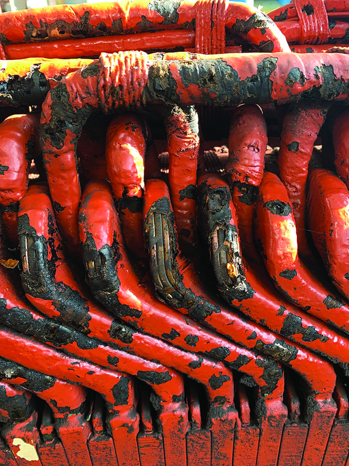
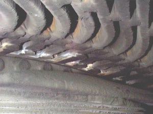
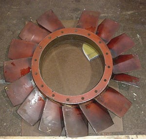
Prevention. Inserting a borescope under the retaining rings can help identify existing insulation migration. Removing the retaining rings can confirm the extent of the problem (Figure 1). Completely rewinding the rotor with Class F insulation and using a proven adhesive to hold it in place is the best long-term solution. Partial rewinds have proven less successful.
1. Creeping out. Exposing the end windings of this GE Frame 7’s generator by removing its retaining rings reveals that insulation has crept out from between the turns. Courtesy: National Electric Coil
Partial discharge
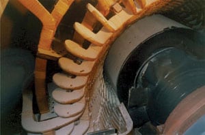
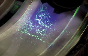
Problem. Partial discharge (PD) failures have been experienced by some newer air-cooled generators after fewer than 10 years of service. PD occurs internal to the coil if the insulation is manufactured with the presence of voids. PD external to the core often occurs in the gaps between the coil and the stator core or in the end turns if the coils are in close proximity. Because the breakdown is partial, the condition does not create a full electrical ground. However, over time, PD can cause enough cumulative deterioration to create a full ground, tripping the generator off line. If PD activity is severe, it can totally destroy the resins and binders of slot filler materials. PD activity is often observed as a discoloration, usually white, of the coil insulation surface (Figure 2).
2. Telltale sign. Evidence of partial discharge activity is the white discoloration on the coil insulation surface of this stator winding of a 9,490-kVA, 600-rpm generator from the UK’s Brush Electrical Machines Ltd. In this case, the PD likely was caused by the lack of a gradient coating in the end turn cell bend area. Courtesy: National Electric Coil
Prevention. PD activity can be monitored while a generator is on-line. But doing so requires inserting stator slot couplers under the stator slot wedges to track the magnitude and frequency of the discharges. Merely detecting PD activity alone isn’t as beneficial as trending it over time, because different machines have different baseline values. For example, if PD levels double over a six-month period, a generator should be opened up and visually inspected. Once PD has damaged a unit, rewinding it with properly designed coils or bars may be the only permanent solution.
Contamination
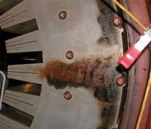
Problem. Contamination by oil, chemicals, or dirt can cause all sorts of generator problems. For generators cooled by hydrogen, maintaining the purity of the gas is critical to their efficient operation and cooling. Oil leaking into a generator can reduce hydrogen purity enough to cause a trip. For air-cooled machines, dirt and dust are a common cause of electrical grounds. Generators sited outdoors or in corrosive environments face similar risks from airborne contaminants. Even fire extinguisher chemicals can cause extensive damage (Figure 3).
3. Condemnation. Fire extinguisher chemicals contaminated this four-pole Brush unit, which was designed to produce 21,150 kVA at 1,800 rpm. Its rotor and stator windings and core were condemned. Courtesy: National Electric Coil
Prevention. Good maintenance practices are the first line of defense against contamination. Hydrogen dryers and leak detectors should be inspected regularly for signs of oil or water intrusion. Desiccants should be replaced regularly and filters for air-cooled units cleaned regularly. Though contamination from accidents may be unavoidable, work and emergency procedures should be reviewed to minimize risks. Insulation resistance tests, and calculation of the PI (Polarization Index) are a good way to gauge a rotor or stator winding’s overall cleanliness.
Stator vibration
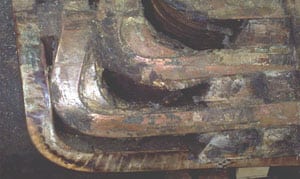
Problem. Vibration of a stator winding’s end turns can cause either or both of the following problems: erosion of coil insulation (precipitating a ground fault) or breakage of coil strands (leading to overheating). Stator vibration, which is caused by double-frequency operating forces, can loosen the end turns over time. Figure 4 shows the telltale greasing produced by end-turn vibration. As the coils’ relative motion wears away their insulation, particles of dislodged insulation mix with entrained oil to form grease. Figure 5 shows the white dusting (caused by contact of the stator coil’s end turns and the support bracket) of the juncture of the bracket and the end-turn surge ring.
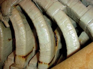
4. Vibration’s damage. The greasing between the coils is symptomatic of end-turn vibration. The grease results from the mixing of entrained oil with particles of insulation dislodged by the relative motion of coils. Courtesy: National Electric Coil

5. Ah, there’s the rub. Note the white powder where the bracket and the end turn surge ring meet. The dusting was created by the relative movement of the stator coil’s end turns and the support bracket. Courtesy: National Electric Coil
Prevention. A "bump" test can reveal if a generator’s stator windings are resonating at 120 Hz, making them prone to vibration problems. Stator windings whose end turns vibrate chronically may have to be retrofitted with a new bracing system. Such a system must be carefully engineered so it decouples the end turns from the stator core and braces them radially while allowing their free axial expansion with temperature changes.
Exciter contamination
Problem. Because exciters are as susceptible as generators to attack by dirt and other contaminants, regular inspections and testing can serve as the proverbial ounce of prevention. Although larger utilities do a number of their own inspections and tests, they and smaller utilities with fewer in-house resources may have to call on outside experts to diagnose problems. Dirt, contaminants, or debris that comes into contact with high-voltage parts can foster the development of short-circuits or grounds.
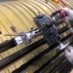
Prevention. Any inspection and testing program should include visual inspections and procedures for removing, cleaning, testing, and reassembling individual components. When an exciter needs to be refurbished, the scope of work should include electrical testing and high-speed balancing (Figure 6) of the exciter assembly.
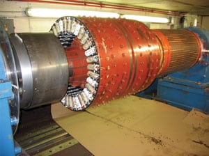
6. High-speed balancing. A high-speed balance of the entire exciter assembly is an important part of a quality exciter refurbishment. The 3,600-rpm Siemens-WH exciter shown—with a nameplate rating of 4,500 kW—is one of only a handful of hydrogen-cooled exciters in operation and among the largest exciters in existence. Courtesy: National Electric Coil
Foreign object damage
Problem. A foreign object can end up inside a generator due to human error or a material failure. In either case, the generator can fail as a result. Once inside the machine, an object that comes into contact with the spinning rotor can wreak havoc on the generator’s internals.
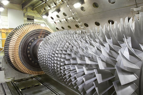
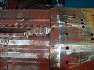
Prevention. Any generator component that can fail or be dislodged—including rotor fan blades (Figure 7), balance weights, slot wedges (Figure 8), bolts, and pantleg washers—should be inspected regularly. Obviously, take care not to leave any inspection, testing, or maintenance tools behind, because they could cause catastrophic damage upon re-start. Pulling the generator’s rotor facilitates more-thorough inspections. Following the visual inspections, do a final crawl-through and remember to perform ultrasonic or magnetic particle tests on critical rotating components. In the case of the fan shown in Figure 7, its replacement was designed to eliminate or reduce harmonic vibratory modes and stresses. The blades of the new fan were made thicker and stronger, significantly increasing their mechanical-resonance frequencies.
7. Cracking under fatigue. Rotating fans can develop fatigue cracks with enough operational cycles—as this one did. Pieces of blades came loose and caused enough damage to require both stator and rotor rewinds. Courtesy: National Electric Coil
8. Wreaking havoc. The failure of a rotor slot wedge also can produce severe damage. Courtesy: National Electric Coil
Fatigue cracking
Problem. Many generator components are susceptible to fatigue stresses that can foster cracking. With rotors, cycling service can cause low-cycle fatigue cracking of forged rotors, including cracks in tooth tops, snap ring grooves and fluted areas, windings, slot wedges, wedge grooves, and retaining rings. The failure of a forged component can initiate conditions that can completely destroy a generator or even cause loss of life. Figure 9 shows cracking of a copper turn—in the blade base area, rather than in a weld joint—that was attributed to low-cycle fatigue stresses. Rotating fan blades are more susceptible to high-cycle fatigue cracking.
9. Tired turn. Low-cycle stresses can lead to fatigue cracking of copper turns. The resulting arcing and burning can cause short-circuits and rotor imbalance. Courtesy: National Electric Coil
Prevention. Regular nondestructive examination (NDE) helps you find cracks early, before a failure occurs and the component has to be repaired or replaced. The choice of inspection method depends on the material, accessibility of parts, and other criteria. Select from among ultrasonic, wet fluorescent magnetic particle (Figure 10), eddy current, and simple dye penetrant testing.
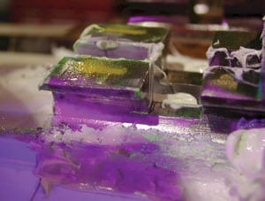
10. Test to prevent cracking. Cracks in a rotor’s snap ring groove can be identified by a wet fluorescent magnetic particle test. Courtesy: National Electric Coil
SCC of retaining rings
Problem. Stress corrosion cracking (SCC) occurs on nonmagnetic retaining rings—particularly those made of 18Mn5Cr alloy steel. The presence of high stresses (retaining rings typically are the most highly stressed component of a generator), moisture, or chlorides will initiate cracking and pitting of this material. Laboratory tests have shown that when conditions are ideal for cracking, cracks can grow as quickly as 0.001 inch per hour.
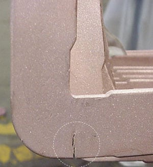
Prevention. SCC of retaining rings can be prevented by keeping them dry. This can be difficult on air-cooled generators because—unlike hydrogen-cooled machines—they are influenced by ambient conditions. Regular NDE, using ultrasonic and dye penetrant testing, can detect cracking early (Figure 11). An alternative—but expensive—approach is to replace the 18Mn5Cr retaining rings with rings made of 18Mn18Cr, a material that is much less susceptible to SCC.
11. Early detection essential. Stress corrosion cracking of an 18Mn5Cr retaining ring revealed by nondestructive examination. Courtesy: National Electric Coil
Rotor winding distortion/turn displacement
Problem. Severe rotor winding distortion and turn displacement can cause shorted turns or electrical grounds. The distortion can be caused by poor design of the end-turn blocking supports or by the lack of an adequate slip plane between the top copper turns and the retaining ring. This causes the top turns to elongate, as shown in Figure 12.
12. Out of whack. Rotor coils or turns can short out when the turns elongate. Because the shorted turns operated at a lower temperature than their counterparts on the opposite pole, the rotor bows, creating an unbalance. Shorted turns also reduce the rotor’s excitation capability. Courtesy: National Electric Coil
Prevention. Proper design of the rotor coils and the blocking supporting the coils under axial loads is essential. In some instances, if only the top turn is distorted, it can be put back into its proper position. Rotors should be tested for turn-to-turn shorts with a flux probe at operating speed. Retaining-ring ground insulation should have a Teflon surface to allow coils to expand and contract with temperature.
Rotor overheating
Problem. An overheated rotor can reduce insulation life and lead to shorted turns and/or ground faults. Overheating usually stems from design shortcomings or abnormal operating conditions. Localized heating often occurs at the interface of the rotor body and retaining ring interface. Darkening of the rotor surface is the usual manifestation of overheating due to abnormal generator operation. Short-term overheating may result from the blockage of ventilation passages by shifting pieces of insulation or slot wedges.
Prevention. Make sure that slot liners and filters and rotor wedges with cooling vents are secured to prevent them from migrating and blocking cooling passages. Always operate generators within their capability curve. For all rewinds, specify Class F insulation and components.
Rotor vibration
Problem. Although rotor vibration is not usually catastrophic, it has caused many forced outages. Most often, the vibration is caused either by shorts, blocked ventilation passages, electrical grounds, mechanical imbalance, wedge or coil stick-slip, loss of balance weights, overheating, or bearing wipe.
Prevention. A good maintenance and inspection program goes a long way toward preventing vibration problems. Well-positioned vibration monitors and alert operators also are essential.
Stator wedge looseness and failure
Problem. Wedges are essential for holding stator coils tight in their slots. They also help minimize vibration from steady-state-related excitation forces. When wedges loosen, coils vibrate and erode ground-wall and turn insulation. Such wear leads to ground failures or turn-to-turn shorts. Should a wedge become completely dislodged, damage to both the winding and core can be extensive.
Prevention. Proper wedge design and installation minimize the potential for movement and vibration. Top, bottom, and side ripple springs preload the coil and maintain compression under all normal operating conditions. It is important to conduct periodic checks during regular maintenance to verify wedge tightness. Prevention of oil seepage into the machine also helps prolong wedge tightness and insulation life. A typical stator wedge has gauge holes for measuring ripple-spring deflection.
Stator core damage
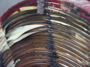
Problem. A stator core can loosen over time as pre-tensioned through-bolts relax. A loose core is susceptible to coil and lamination damage. If laminations vibrate relative to one another, they can cause wear of surface insulation. Such wear leads to shorts, core hot spots, and—eventually—core-to-core or coil-to-core failure. Note that in Figure 13, the arc damage to the surfaces of the lamination was not visible until after the core was unstacked.
13. Surprising stator. The arc damage to the surfaces of the lamination was invisible until the stator core was unstacked. The generator shown is a 3,600-rpm Westinghouse unit rated at 493,000 kVA with a direct hydrogen-cooled, double-tube stack winding. Courtesy: National Electric Coil
Prevention. Inspection of through-bolt tightness is recommended at regular intervals. Regular EL CID (electromagnetic core imperfection detection) tests or loop test inspections of the stator core can be used to verify its continued integrity. The knife test is an even simpler way to check for stator core looseness.