U.S. power producers and owners of industrial steam systems each spend about $15.4 billion annually to combat corrosion in their plants. Scale and deposits are thought to be responsible for another $20 billion a year in reduced plant efficiency and lost generation capacity. Corrosion is the primary cause of every other forced outage, and the amount of money being spent to repair it (Table 1) would suffice to build ten 1,000-MW power plants each year.
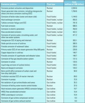
Table 1. A breakdown of the yearly costs of corrosion problems by plant type Source: Based on B.C. Syrett and J.A. Gorman, "Cost of Corrosion in the Electric Power Industry—An Update," Materials Performance Magazine, Vol. 42 (February 2003); original information source: Cost of Corrosion in the Electric Power Industry, EPRI Report 1004662 (Palo Alto, CA: 2001).
Localized corrosion can occur in any environment characterized by high stress, weak materials, and/or high concentrations of corrodents. Localized corrosion can take any of several distinct forms, such as stress corrosion cracking (SCC) of steam turbine blades, boiler-tube failures caused by corrosion fatigue (CF), and low-cycle corrosion fatigue (LCCF), pitting, and flow-accelerated corrosion (FAC) of steam-cycle components.
Contributors to localized corrosion include inattention to the effects of stress, flow, and heat transfer during steam-cycle and component design, weak materials, and poorly designed and operated water chemistry regimens. Each factor plays a similarly important role: Statistics from one insurance company indicate that mechanical problems (48%), thermal issues (25%), and water chemistry upsets (27%) are the three primary root causes of SCC.
Water treatment isn’t the only plant operation that can foster corrosion if it’s not executed and watched like a hawk. Another is more-frequent cycling. The system and component designs of older plants did not anticipate end users starting them up and shutting them down every day—an increasingly common practice. Each start-up and shutdown creates thermal and mechanical stresses that are as conducive to corrosion as excessive levels of chlorides or NaOH in boiler feedwater.
Fighting corrosion: A team effort
Levels of all types of corrosion seen in steam-cycle systems (Figure 1) can be reduced by attending to their root cause(s) during cycle and component design and operation. The potential for SCC of any component, for example, is a function of three primary variables: the material the component is made of, the mechanical stress it is asked to bear, and its operating environment (Figure 2). Often, two or more of these factors work in combination. For example, SCC is more likely when the tensile stress imposed on a component exceeds its threshold design value and the interaction between its material and its environment fosters cracking.
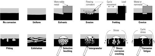
1. Dirty dozen. Corrosion mechanisms potentially active in steam cycles. Source: Jonas Inc.
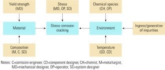
2. Shared responsibility. The primary (in blue) and secondary causes of corrosion cracking and the engineering specialists who should be responsible for controlling them. Source: Jonas Inc.
Figure 2 also shows the secondary contributors to the three primary SCC variables—and who should focus on minimizing their contributions. Reducing stress in a steam-cycle system, for instance, is the joint responsibility of the mechanical designer, the system designer (who should make it possible to operate the system within control limits), and the operator (who must follow specified procedures). Similarly, the mechanical designer should ensure that a material has sufficient yield strength, whereas a metallurgist, corrosion engineer, and the system designer together focus on its chemical composition, microstructure, and heat-treatability.
Minimizing the potential for SCC effects caused by the component’s environment is likewise a joint effort. The average bulk environment is decided by the system designer, who chooses the thermodynamic and flow parameters of water and steam. Temperature is the most important variable to consider in the design of liquid-phase components, but the effects of pressure and moisture content also should be accounted for by designers of steam-side components. If system and component designers are attentive to impurities that could leak into the steam cycle or be generated internally (by boiler blowdown, condensate polishing, and/or filtration), operators will be able to detect and remove them. Avoiding excessive generation of corrosive species obviously should be the responsibility of water chemists. Finally, all parties should collectively evaluate the transport of impurities and water treatment chemicals around the cycle (Figure 3), because the results will bear on materials selection—in particular the compatibility of materials with the type of treatment method chosen.

3. The right dose. Transport of chemicals and corrosion in a steam cycle. Source: Jonas Inc.
Good and bad cycle designs
The design features and parameters of steam cycles that influence local water chemistry and corrosion include:
- The type, size, pressures, and temperatures of the steam generator. Tradeoffs in the materials of steam-cycle components pit all-ferrous materials vs. steels and copper alloys.
- Plant operating mode (baseload vs. cycled, minimum load, loading rate).
- The ability to remove corrosion products by filtering, condensate polishing, and boiler blowdown.
- The type of water treatment process chosen.
- Sampling equipment and instrumentation.
- Layup provisions.
- Sources of makeup water and its treatment.
- Control of condenser leaks, air in-leakage, and return condensate.
- Start-up provisions (cleanup loops, turbine bypass, filling).
Two examples of good steam-cycle designs are drum and once-through boilers with no copper components, tight condensers, and/or condensate polishing. An example of a marginal cycle design would be an original pressurized-water reactor steam generator. Such units had large pre-boiler cycles with high flow velocity. Some had condensers and feedwater heater tubing made of copper alloys. In many cases, these design features precluded condensate polishing and led to leaking condensers, high air in-leakage, ineffective steam generator blowdown, and the presence of up to 75 ppm of chloride in the steam generator.
A multidisciplinary checklist
Each of the following five design disciplines manipulates different variables (in parentheses) to minimize the potential for corrosion in steam cycles:
- Mechanical design (stress, vibration, stress concentration, stress intensity).
- Heat transfer (surface temperatures, temperature changes, heated crevices, boiling, evaporation of moisture).
- Flow (moisture and liquid velocity and turbulence, vortex shedding, stagnation temperature, interaction of shock wave with the Wilson line).
- Physical shape (crevices, flow, surface finish).
- Materials (corrosion characteristics, residual stresses, maximum yield strength, toughness, damping, etc.).
The above effects (which influence one another) can produce undesirable stresses and impurity concentrations. For example, putting certain dissimilar metals in contact can produce galvanic corrosion. New designs, redesigns, and failed components should be carefully checked for their ability to meet corrosion-related requirements.
Table 2 is a proposed checklist of corrosion design requirements that takes into account the interactive nature of the variables listed in parentheses above. Because there is no uniform relationship between corrosion and fatigue properties of smooth, notched, and cracked surfaces, the checklist contains fracture mechanics parameters (KISCC, ?KTH, etc.) as well as properties of materials without flaws (sSCC, fatigue limit, etc.). It is a supplement to—not a substitute for—other steam-cycle equipment design practices.
Because there are strong interactions between the five sets of variables, all steam-cycle surfaces should be checked against the checklist for different operating conditions—including transients and layup. Strain cycling and multi-axial tensile stresses increase the propensity for localized corrosion. Because there are little quantitative data on these effects, they should be taken into account by using more conservative designs (that is, using high safety factors).

Table 2. Proposed checklist of corrosion design requirements Source: Jonas Inc.
The role of in-situ environment
Besides control of average bulk water and steam chemistry, control of the in-situ environment at metal surfaces (by design and chemistry) is essential, because this is where localized corrosion occurs. Component design features such as heat transfer, flow, and shape interact with bulk chemistry to determine the "microclimate" at component surfaces.
This climate can be quite corrosive if one or more of the following conditions exists:
- The concentration of impurities is sufficient to foster the formation of concentrated aqueous solutions ("salt zones")
- There is insufficient control of pH (in both acid and alkaline regions) by water treatment additives such as ammonia.
- The pH of moisture droplets and film is suppressed.
- There is high turbulence caused by a flow obstruction or high velocity.
Figure 4 depicts such a situation of a general sort. It is a Mollier diagram representing a turbine steam expansion line and thermodynamic regions with high concentrations of impurities (including NaOH, salts, and acids). The areas and types of the resulting corrosion also are shown.

4. Thermo 101. Mollier diagram of a drum boiler cycle showing regions of impurity concentration and corrosion. Source: Jonas Inc.
Note that hot (in relation to steam saturation temperature) surfaces can shift from the liquid and wet steam region into the salt zone and above. This is why turbine disc SCC occurs in the wet steam regions and why there is high concentration of impurities and corrosion in boiler tubes, in heated crevices of pressurized water reactor steam generators, and elsewhere. It also makes clear why local surface temperatures and environments should be considered during design and in failure analysis. The surfaces may become hot due to heat transfer through the metal of heat exchangers (or even that of the turbine), or due to the "stagnation temperature" effect—a zero flow velocity at a surface where the kinetic energy of steam changes into heat.
The mechanisms that elevate concentrations of impurities in low-pressure turbines (Figure 5) include:
- Evaporation and drying of moisture on hot surfaces.
- Precipitation from superheated steam and deposition.
- Concentration in oxides.
- Adsorption and heterogeneous nucleation of concentrated droplets and crystals on surfaces.
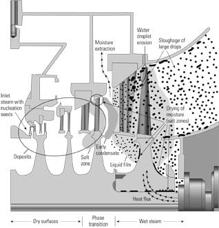
5. Where to look. Cross section of a low-pressure turbine highlighting where physical-chemical processes are active. Source: Jonas Inc.
Although the in-situ environment at component surfaces has been studied, it is usually estimated from the composition of bulk water and steam, local pressures and temperatures, and available chemical thermodynamic data. The environment depends on the chemical species present as well as their dissociation, volatility, solubility, and other properties.
Other corrosion conditions
The need to minimize corrosion isn’t limited to the design and operation of steam-cycle equipment. Contaminants can enter systems and later wreak havoc during their:
- Manufacture (machining fluids, lubricants, etc. must be controlled).
- Storage (when airborne impurities and preservatives can enter).
- Erection (when equipment is exposed to air pollutants, preservatives, and cleaning fluids).
- Chemical cleaning.
- Nondestructive testing (cleaning and NDT fluids can foster corrosion).
- Layup (low pH, water with high oxygen content, deposits, and humid air must be avoided).
The unanticipated interactions of contaminants and environments can produce very negative results, such as the following.
Acid damage. Preservatives and machining, cleaning, and NDT fluids may contain sulfur or chlorine, each of which could form acids upon decomposition. Decomposition of organics starts at about 300F. The concentration of sulfur and chlorine in preservatives and fluids should be limited to 50 to 100 ppm. Any residual fluids should be removed before operation.
SCC of superalloys and steels. Molybdenum disulfide (MoS2) has been known to cause SCC of superalloys and steels by producing a local acidic environment. Its oxidation products form low-pH solutions of molybdic acid. Ammonium molybdate, into which turbine operation turns MoS2, can rapidly attack the turbine steels. MoS2 has been used both as a thread lubricant and during assembly of turbine disc-rotors, when the discs are preheated and shrunk on the rotor. During this process, MoS2 can oxidize to MoO3, later yielding molybdic acid on contact with H2O. Analysis of disc bore and keyway surfaces often reveals the presence of molybdenum and sulfur. In steam, MoS2 has reduced the notch strength of disc steels by about 30%. It also has been implicated in failures of bolts and rotor shafts.
Galvanic corrosion. Graphite products, such as gaskets and bearings, can introduce galvanic corrosion where the more noble graphite acts as a cathode against steel.
Layup conditions. Layup schemes—including wet layup (water with a low oxygen content in combination with high concentrations of ammonia and hydrazine), dry nitrogen blankets, preservation by cleaned dehumidified air, and the use air with vapor-phase inhibitors—decrease the potential for corrosion. It often is difficult to control local conditions in a large complex system, particularly after corrosive impurities have accumulated during operation.
Sketchy design data
Corrosion data are needed for two groups of environments:
- Water and steam without impurity concentration. The concentration of oxygen should be as specified or as measured (high oxygen is often only a transient condition). Carbon dioxide is a very important ever-present impurity that is often neglected in testing. Trace impurities, such as metal (Fe, Cu, Ni, Pb) oxides, play a key role in corrosion cracking and should be a part of the test environment. For control of FAC, the definition of the environment should include its flow velocity, turbulence (shape factor), temperature, pH, and concentrations of oxygen and oxygen scavenger.
- Concentrated impurities (salts, acids, and hydroxides). Testing in calculated environments or simulated service testing (heated crevice, capsules, etc.) is necessary to represent local impurity concentration mechanisms. Corrosion testing with and without impurity concentration often can be best performed in the field with the actual service environment drawn into a test rig from the steam cycle or with test specimens directly inserted into the cycle components. This considerably reduces the size of the test matrix and ensures a representative environment.
Use Table 2 as a guide to the types of design data required. Corrosion data are scattered through the technical literature and in the original equipment manufacturers’ and architect-engineers’ proprietary design rules. Most boiler design codes provide little help, but the American Society of Mechanical Engineer’s Boiler and Pressure Vessel Code does recommend corrosion allowances and considers corrosion fatigue crack growth (in Section XI). Other standards organizations such as NACE International, ASM International, American Petroleum Institute, and EPRI have published some data and recommendations for avoiding corrosion through best-practices design and operation.
Lessons learned
Over the years, there has been no shortage of mistakes made during the design and O&M of steam-cycle and water chemistry systems and equipment (Table 3). Against this backdrop, and to conclude this article, here is some practical advice.

Table 3. How to invite corrosion during steam-cycle design and O&M Source: Jonas Inc.
Cycle design. Be sure that system design, materials, and water treatment are compatible. Because some impurities will always find their way into the system, be sure to provide a mechanism (boiler blowdown, condensate polisher, deaerator) to prevent them from accumulating. Avoid using copper or copper-alloy tubing, because it makes control of feedwater chemistry and corrosion difficult.
Component design. Corrosion control by component design is an interdisciplinary task combining stress and vibration, heat transfer, and flow. It includes:
- Steady and variable stresses and stress concentrations (Table 3)
- Material defects
- Maximum yield strength
- Heat flux
- Vortex shedding vs. resonance
- Flow velocity and turbulence (FAC and cavitation)
- Galvanic and crevice effects
Water chemistry. The cycle and component design should be for a specific cycle chemistry with the goal to avoid concentration of chemicals (scale and corrosion), decomposition of organic water treatment chemicals and impurities, and harmful chemical reactions (hideout). The control should include control of impurity sources (makeup, condenser leaks, air in-leakage, return condensate) and control of boiler carry-over to protect the turbine. The best water chemistry control can be achieved in the plant design phase: water treatment, tight condenser, steam drum separation, and sampling and instrumentation.
Otakar Jonas can be reached at 302-478-1375 or jonasinc@steamcycle.com.