The technology and materials within hydropower plants have advanced substantially over the last century. This has required plant owners and operators to take a more proactive approach to maintenance and upgrades of generators and control systems. Scheduling repairs in conjunction with an ongoing predictive maintenance program, and developing a good working relationship with a trustworthy repair partner, can minimize operational downtime and increase productivity.
Hydroelectric power is one of the oldest forms of renewable energy in the world. In September 1882, the first hydroelectric power plant began operation on the Fox River in Appleton, Wisconsin. It had a capacity of about 12.5 kW and supplied power directly to the home of H.J. Rogers, Appleton Pulp and Paper Co., and the Vulcan Paper Mill. Nearly 138 years have passed, but hydroelectricity still powers the world using the same basic concept, only with a more advanced approach to construction, operation, and maintenance.
By establishing a repeatable and clear evaluation process that includes both onsite maintenance staff and a reliable repair partner, managers can ensure the most critical hydroelectric equipment in the plant stays efficient and operational. The responsibility of the hydroelectric power plant’s repair partner is to suggest the proper materials and procedures to repair or upgrade a unit. The operator carries the responsibility of identifying potential issues as they arise. This teamwork between operators and technicians help maintain plant reliability and ultimately keep the lights on for subscribers.
Visual Inspections
Many potential issues can be found with routine visual inspections by the operator or repair partner. These can include insulation deterioration, arcing, vibration, and temperature rise. After these observations are made, the operator should then pass the information to management with suggestions of next steps to keep the generator running.
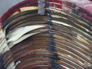
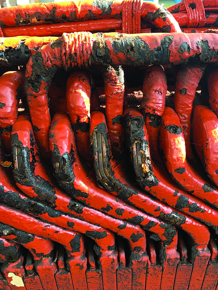
When a generator is offline, the plant operator should take that time to do a routine visual inspection. They should examine the generator winding with a flashlight, looking for any signs of insulation deterioration (Figure 1). Insulation deterioration can present itself in the form of cracking, flaking, or unraveling.
 |
|
1. Signs of insulation deterioration in the generator winding include cracking, flaking, and unraveling. Courtesy: Jenkins Electric |
As the insulation breakdown worsens, the ability for contamination, such as water, to enter the circuit increases. Contamination can lead to turn shorting and grounding to the stator or rotor frames. Monitoring the rate of deterioration will allow the plant management team to schedule generator downtime for testing, cleaning, and reinsulating. Preventive maintenance will keep repair costs down and extend the life of the current winding before rewind is required.
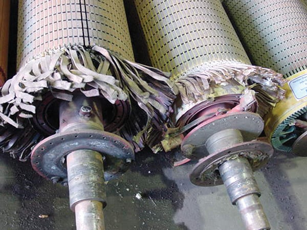
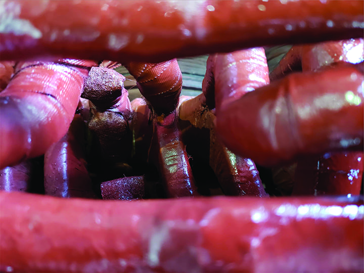
Contamination can present itself when insulation deterioration is not immediately evident. A buildup of dirt and oil can mask the presence of bad insulation (Figure 2). Only with cleaning and testing can the insulation be verified for safe operation.
 |
|
2. The presence of dirt and oil can make it difficult to thoroughly inspect insulation. Courtesy: Jenkins Electric |
The most common and widely accepted onsite cleaning method is cryogenic—or dry ice blasting. This method involves using dry ice pellets through a blasting rig similar to sand blasting. The pellets freeze the contamination that is stuck to the generator and the subsequent pass knocks it free.
Cleaning with this method is cost-effective, efficient, and requires less downtime. This method does not introduce additional moisture due to the carbon dioxide evaporating into a gaseous form. Once the contamination is removed, the insulation can be visually inspected and electrically tested for viability.
Testing
Testing should be performed prior to cleaning to obtain baseline readings. An initial test for moisture should be the first check. With all safety measures in place, the stator and rotor should be checked with a multimeter that will read in the millivolt scale. One lead of the multimeter is attached to a winding lead and the other to ground. Any reading greater than 20 mV should be considered wet and will require drying using tarps and heaters or “fanning” the unit.
Fanning is performed by opening the gates and rolling the unit while offline. This will allow air to circulate and dry the unit. Once the millivolt reading is acceptable, further testing can be performed.
An insulation resistance (megger) and polarization index test set to the appropriate voltage will determine the condition of the ground wall insulation, and further detect contamination or moisture. Once the stator winding reaches 10 megohms (MΩ) and rotor reaches 1 MΩ, the unit is acceptable to continue with further testing. Should the megger test results be at an acceptable level, a dielectric withstand test (also known as a high-potential or hipot test) can be performed to ensure final acceptance of ground wall insulation. If the megohm reading does not increase to acceptable levels, further cleaning, inspection, and additional ground wall testing may be required.
Potential Issues and Repairs
If the stator ground wall insulation fails testing and there is no visual evidence of a failed coil, the fault can be isolated by systematically opening the connection and retesting until the fault is located. The technician will split the winding in order to determine which of the winding halves the failed coil is located within. The investigator will then continue to halve the coils on the failed side until the failure is located.
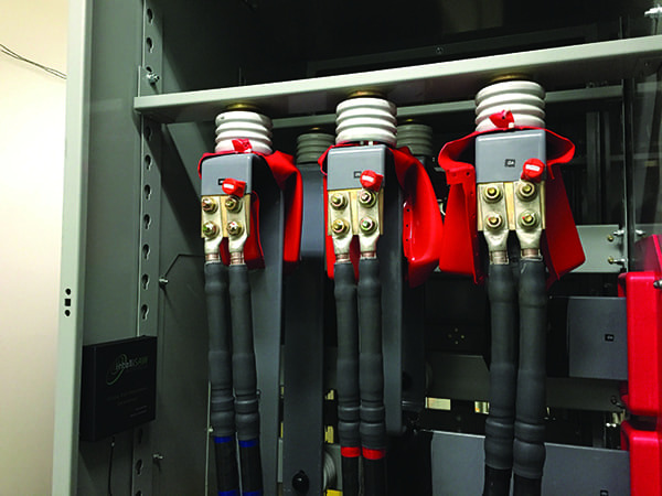
At that point, a decision must be made to either cancel the coil (Figure 3) or rewind the stator. Coil canceling requires the end turns of the failed coil to be cut and bypassed. There is no firm rule to determine the number of coils that can be removed from the circuit, and engineering judgment should be used to determine the performance effects of coil losses. Coil canceling is only a temporary repair option until downtime and funding can be allocated to a rewind.
 |
|
3. Coil canceling requires the end turns of the failed coil to be cut and bypassed. Courtesy: Jenkins Electric |
The rotor circuit analysis should include the same stator tests along with a voltage drop test. This test is used to evaluate the turn-to-turn insulation in the rotating fields. To perform the test, 120 VAC is applied to the circuit and the voltage drop is measured across each field pole. The resulting readings should all fall within +/–10% of the average. Any reading outside of this range indicates contamination or insulation failure, resulting in turn-to-turn shorting. The bad poles can then be removed for repair or rewinding.
Collector Ring Assembly Considerations
Monitoring brush wear and collector ring condition is also critical to long-lasting performance. The rings should be concentric with the shaft to avoid lifting of the brushes. When a brush lifts off the collector rings an arc will occur and create a pit in the surface of the ring. This will cause premature wear of the brushes and incur more material cost along with more downtime cost.
Collector ring resurfacing can be performed in a repair partner’s machine shop or onsite. The onsite repair of collector rings can only be done if the location can be made safe enough for a machinist to work. This will require custom temporary machine guarding to be fabricated and installed. The rings should then be turned concentric with the generator shaft and stoned to an appropriate surface finish of 32 Ra (roughness average).
Spring tension must also be kept, ensuring brush lifting does not happen. Older styles of brush holders use arms with a tensioner coil attached with adjustment slots for increasing tension as brush wear occurs. This requires operators to adjust tension as brush life is reduced. If not done at the correct frequency, brush lifting can occur—resulting in arc damage to collector rings.
Most brush manufacturers offer to fabricate new brush holders with a constant force coil spring that eliminates this issue. The new design allows for the contact pressure between the brush and the collector ring to remain constant, even with an eccentric ring. This allows for more consistent predictable wear, and removes the downtime of the operator adjusting the spring tension. This new style of holder can be designed as a direct replacement with no modification required, providing consistent predictable wear that eliminates unnecessary stopping for spring tension adjustment.
Repair and Testing Documentation
Any time work is performed on a generator, the test data and work performed should be documented for historical purposes. Future repairs can be compared against this data for trending. For repair partners, having the data will give them a guide of what to look for and will expedite the evaluation process. If they know what the symptoms and the solutions in the past have been, it will point them in the right direction to get answers quickly, minimizing downtime expenditures.
All the tests and observations can and should be integrated into a preventative maintenance program. Repair partners can help design and implement this program, and working together with owners, can lower operating and maintenance costs, and keep critical equipment running reliably. Planning for repair downtime and periodic upgrades is made easier when owners and repair partners have a cohesive plan, historical data, and best practices in mind, while working together to keep the lights on for millions around the world. ■
—Ryan Ossmann is the repair operations manager at Jenkins Electric. He is a trained machinist with more than 22 years of experience in the motor repair industry.