Solving insidious vibration problems in rotating equipment may sometimes seem like a black art that requires the right incantation. But identifying the root cause of the vibration is actually a science. By using cutting-edge vibration measurement tools in concert with computer simulations, plant operators can arrive at a permanent, cost-effective solution to virtually any vibration problem.
Every pump and turbine in a power plant has a spinning rotor whose synchronous (once-per-revolution) vibration levels should be monitored closely. There’s no escaping that need; even the best millwrights in the business cannot perfectly mass-balance a rotor. Vibration problems never go away. They only worsen over time, potentially causing forced outages and unnecessarily large expenditures for repairs, spare parts, and/or labor-intensive O&M.
Excessive machinery vibration is common in power plants, which are home to large machines with long multi-bearing drivelines that are sensitive to alignment, rotor mass balance, and internal liquid and gas forces on rotating components. Good vibration trending data may allow plant operators to identify an emerging vibration problem before equipment damage can occur (Figure 1).
|
1. Predictable and unpredictable. Tracking vibration trends in rotating equipment. Source: Machinery Vibration Inc.
|
Given the number of rotating machines in power plants, it’s surprising that many vibration problems are not rigorously addressed for years, until someone new to the plant makes them an issue. That’s because many plants’ “tribal knowledge” categorizes vibration as a maintenance problem requiring, for example, frequent rotor balancing. The impact of chronic vibration problems cannot be overstated; these problems make it more difficult for operators to start up and shut down units and to place units in load-following mode. Even state-of-the-art vibration-monitoring systems equipped with diagnostic routines may not help in troubleshooting, because they lack enough parallel computer simulation models.
Nonetheless, several recent cases underscore the cost-effectiveness and efficacy of using cutting-edge measurement and simulation tools together to troubleshoot rotating machinery vibration problems. Following are some typical vibration anomalies observed in power plants.
Load-following critical speed in a 240-MW turbine
When a 240-MW steam turbine-generator spinning at 3,600 rpm was asked to transition between load levels in the 145- to 185-MW range, its rotor vibrated excessively. Significantly, the unit had been commissioned for baseload operation and had never before been operated in load-following mode.
Measurements along the unit’s entire driveline while in load-following mode suggested that the vibration was due to the unit’s high-pressure/intermediate-pressure (HP/IP) rotor reaching a critical speed. The compelling evidence was a sharp change in the measured phase angle between 190 MW and 200 MW. The preliminary diagnosis was that the HP/IP bearing’s static loads (and, therefore, its stiffness) were changing commensurate with the variable partial emission of the turbine’s impulse/control stage (Figure 2).
|
2. Driveline model. The rotor vibration model for a 240-MW, 3,600-rpm Westinghouse turbine-generator. Source: Machinery Vibration Inc.
|
To confirm the diagnosis, engineers used free software (see Maurice L. Adams, Rotating Machinery Vibration: From Analysis to Troubleshooting [New York: Marcel Dekker, 2001]) to model the entire driveline of the turbine-generator. Simulations verified that the root cause of the vibration was a migrating rotor second critical speed, and the results of these simulations are summarized in Figure 3. The bell-shaped curves at the top of the figure made clear that in load-following mode, changes in the static load on the two bearings supplied with the unit were causing variations in journal oil-film radial stiffness. Even more importantly, the simulations predicted that replacing the original equipment manufacturer (OEM) bearings with 6-pad journal bearings specifically engineered for the unit would attenuate the vibration levels in the 145- to 185-MW range as well as provide consistent levels of vibration over the entire operating range. This bearing replacement eliminated the HP/IP rotor’s second critical speed from its operating power range and allowed for a greater range of load following in this unit, just as the model indicated it would.
|
3. Huge improvement. Simulated vibration levels before (bell-shaped curves) and after (flat line) a bearing retrofit. Source: Machinery Vibration Inc.
|
Feedpump failure due to critical speed
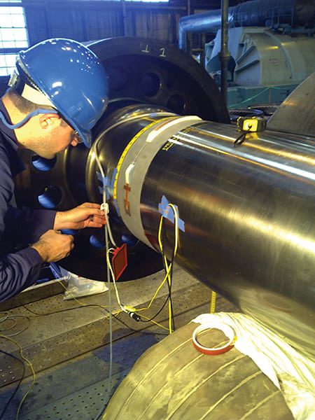
At another plant, excessive vibration within a boiler feedpump caused several forced outages. During one such event, the pump’s shaft suffered a complete through-fracture at a point just adjacent to the balancing drum runner. Initial inspection of the pump by the authors revealed that the pump shaft was not instrumented with any permanent vibration-monitoring equipment. Therefore, the first step taken was to retrofit two noncontacting proximity probes 90 degrees apart near each pump journal bearing in order to obtain the vibration displacement measurements needed to diagnose the problem.
Before collecting data from the probes, a model of the pump shaft was constructed. The simulation predicted that at its normal, full-load operating speed of 5,300 rpm, the pump was operating very close to one of its critical speeds (Figure 4, left). Subsequent reduction and analysis of the roll-up vibration data measured from the retrofitted probes clearly showed a vibration peak at approximately 5,100 rpm (Figure 4, right). An impeller wear-ring modification with pump-specific geometry was engineered to shift the critical speed well above the pump’s operating range.
|
4. Predicted vs. measured. Boiler feedpump shaft vibration as predicted by a computer model (left) and measured (right). Source: Machinery Vibration Inc.
|
Excessive shaft clamping forces in a feedwater pump
Southern Company’s Vogtle Nuclear Plant in Georgia houses two 1,150-MW pressurized water reactors, each served by two 50% feedwater pumps. All four pumps’ rotors had at times experienced cyclic vibration spikes that seemed synchronous with seal injection water flow control. The correlation between pump seal injection water control and vibration was apparent from a 50-minute sample of vibration data (Figure 5).
|
5. Mirror images. A 50-minute vibration record of feedwater pump “B” of Vogtle Nuclear Plant Unit 2. Source: Machinery Vibration Inc.
|
Initial efforts at rotor modeling did not expose any fundamental root causes of the problem. The next step was to pursue an analysis of the cyclic thermal bowing of one of the pump rotors. Upon close examination of the pump, it was observed that the two mating sleeves on each axial side of the shaft’s impeller were rigidly clamped axially by two nuts, one on each end of the shaft just outside the journal bearings. Based on a calculated 10-degree F differential thermal expansion for the sleeves, the thermally induced axial shaft growth was computed to be 1.2 mils. This axial growth resulted in a 23,000-lb compressive force on the sleeves, which was offset from the centerline of the shaft. This offset force, in turn, caused a shaft bending moment of 40,250 in-lb that produced a 3.8-mil transient thermal bow of the shaft (Figure 6).
|
6. Under pressure. The predicted bow of the shaft of a nuclear plant’s feedpump, based on calculated sleeve-to-shaft differential thermal expansion. Source: Machinery Vibration Inc.
|
Shop testing of the plant’s spare feedpump rotor on a balancing machine with locally heated shaft sleeves confirmed the authors’ diagnosis. To correct the problem, the authors suggested adding a compressible gasket under both shaft-sleeve retaining nuts. The low-cost retrofit more evenly distributes the compressive force circumferentially, while freely allowing inherent cyclic differential thermal expansion and maintaining the nominal sleeve assembly’s compressive force. After all four of the Vogtle Plant’s feedpumps were modified in this way, the cyclic vibrations disappeared.
Worn brushes cause shaft to vibrate
At yet another plant, the brushes of the collector stub shaft of a 250-MW, 3,600-rpm steam turbine-generator’s exciter had a history of high wear. As a result, the shaft’s collector rings had to be ground and polished frequently to avoid “flash-over” arcing, a phenomenon that occurs when the collector brushes do not remain in contact with the rings due to large radial excursions. Such excursions are produced either by rotor vibration or by any collector-ring run-out from circumferentially non-uniform wear.
After noting that the collector shaft lacked displacement proximity vibration probes, the authors installed X and Y probes 90 degrees apart to target the outboard end of the shaft. Recorded collector-shaft vibration measurements on roll-up (Figure 7) showed peaks at 3,000 rpm and near 3,600 rpm. A simulation by a rotor vibration model confirmed the vibration peak at 3,000 rpm to be the generator’s second critical speed and the peak at 3,550 rpm to be a critical speed of the a collector stub shaft.
|
7. Twin peaks. The measured, once-per-revolution vibration component of a generator exciter’s collector shaft. Source: Machinery Vibration Inc.
|
The computer model predicted that increasing the weight of the disk at the outboard end of the collector shaft would lower the collector shaft’s critical speed by 300 rpm, moving it well below the shaft’s normal operating range. A reasonably simple, cost-effective fix was made, and the exciter was returned to service.
A cure for steam-whirl vibration
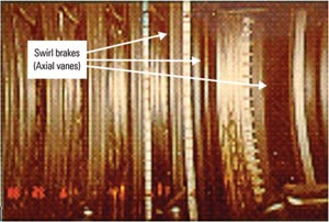
Turbomachinery vibration problems may not have an external cause. Rotors may experience self-excited vibration if they become dynamically unstable as a result of phenomena such as oil whip and steam whirl. Indeed, the HP rotor of the turbine-generator that powers Unit 1 of Tennessee Valley Authority’s (TVA’s) Cumberland Power Plant in Tennessee experienced such severe steam-whirl vibration that the unit had to be temporarily de-rated from 1,300 MW to 900 MW. The authors employed a model-based analysis in order to verify TVA’s initial diagnosis of a steam whirl-induced rotor vibration at 28 Hz (Figure 8). The problem was eliminated by retrofitting “swirl brakes” at the mid-span chamber and tip seals of the first three stages of the unit (Figure 9). Following the modification, Unit 1’s capacity was re-rated to its nominal level of 1,300 MW.
|
8. Whirled, not stirred. A computer model can predict points of dynamic instability along a rotor’s axis. Shown is a 28-Hz vibration caused by steam whirl within a 1,300-MW cross-compound steam turbine-generator. Source: Machinery Vibration Inc.
|

|
9. Hit the brakes. The axial vanes that now serve as the “swirl brakes” of the 1,300-MW turbine’s HP rotor. Courtesy: Machinery Vibration Inc.
|