Monitoring steam turbo-generators in a typical thermal power station is normally straightforward without any particular issues, but Huntly presented special challenges. When the time came to replace the legacy monitoring system, very demanding monitoring requirements had to be fulfilled.
Huntly Power Station, the largest thermal power station in New Zealand, is owned and operated by Genesis Power Ltd., one of four state-owned enterprises that made up the former New Zealand Electricity Department. Huntly was originally built to operate four 250-MW units, which were commissioned from 1981 to 1985 (Figure 1). Since 2004, a 385-MW combined cycle plant, Unit 5, and a 50-MW gas turbine for peaking, Unit 6, were added to the power station.
 |
|
1. Huntly Power Station is New Zealand’s largest power station by capacity. It is located about 90 kilometers (56 miles) southeast of Auckland, New Zealand’s largest city. Courtesy: B&K Vibro |
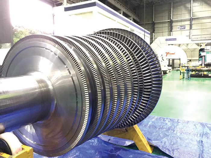
The original units, Units 1 to 4, each consists of a 250-MW turbo-generator, a steam turbine (single reheat cycle), and steam-driven main boiler feed pump. A unique feature of these coal and gas-fired units is that they are mounted on a steel support structure (Figure 2) to provide protection in the event of an earthquake.
 |
|
2. One of the flexible steel beam support structures designed for earthquake protection is shown here from a distance (left) and up close (right). Courtesy: B&K Vibro |
Unit 3 has since been retired from service, and Units 1 and 4 have been operating to system requirements with Unit 2 normally dry-stored. This has just changed recently, however, because the New Zealand hydropower storage capacity is well below average for this time of year and wind power is down. Therefore, all three units (1, 2, and 4) are currently running to conserve water for the predicted dry winter this year.
One Problem Solved, Another Created
The steel foundations serve an important function from a safety point of view, but proved to be a headache because of their structural flexibility. The inboard bearing of the generators (bearing #7) has historically been subjected to high vibration at running speed due to a 100 Hz resonance in the flexible cross beam to which the bearing pedestal was mounted, and a lack of horizontal stiffness in the bearing pedestal. This was compounded by another resonance just below running speed during run-up, caused by the second critical speed of the two-pole generator shaft. If there was a couple imbalance, the critical speed vibration would be excessive during run-up.
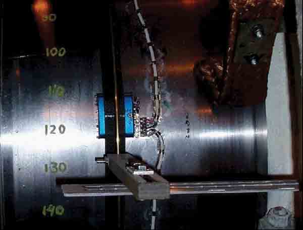
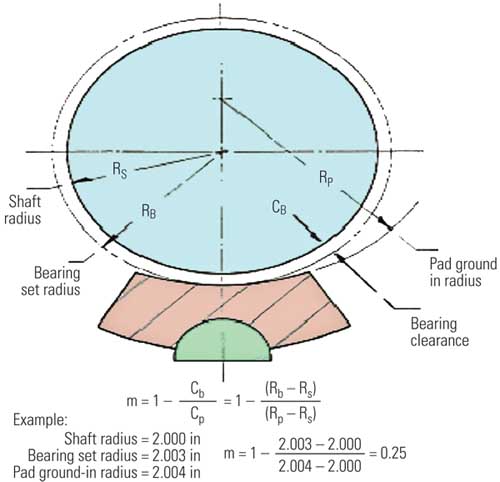
Several solutions were considered to stiffen the structure, but the only option available at reasonable cost was to fit dynamic vibration absorbers to the bearing pedestals. A dynamic vibration absorber is a relatively small auxiliary weight attached to the structure by a flexible steel shaft that acts as a spring, as illustrated in Figure 3. The combination of the length of the shaft and the mass of the weight is tuned so that the auxiliary weight resonates at the same frequency as that which is creating the original problem, which in this case was 100 Hz.
 |
|
3. Dynamic vibration absorbers as seen from bearing #7. (These were mounted on all four units.) Courtesy: B&K Vibro |
The effect of adding the absorber was to split the original resonance into two, one at a slightly higher frequency and another at a slightly lower frequency. As the operational speed is constant, moving the resonance away from the rotational speed reduced the vibration at operational speed, however, it added a resonance into the machine run-up. The upper frequency resonance did not present a problem because it was above the operating speed.
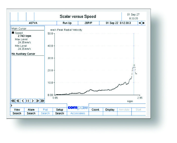
Even with a reduced 100 Hz horizontal resonance and a reasonably good state of balance, the overall vibration was still high at 24 millimeters/second (mm/s) at 2,750 rpm during run-up. This was because the overall vibration is the vector sum of the horizontal resonance plus the 1X running speed vibration that results from being so close to the second critical speed of the generator rotor at 2,800 rpm, which cannot be reduced (Figure 4). The overall vibrations during run-up at machine speeds from 2,750 to 2,850 rpm can be significantly higher if unbalance is present.
 |
|
4. Generator shaft bandpass vertical-axis vibration, 10 Hz – 1 kHz, during run-up. This is a vector sum of the 1X running speed vibration that passes through the generator shaft critical speeds and other component natural frequencies, together with the 2X running speed resonance (100 Hz). The 100 Hz resonance is the dominant frequency component. Courtesy: B&K Vibro |
Monitoring System Challenges
In 1994, Genesis Energy installed the B&K Vibro Compass Classic monitoring system on all four 250-MW turbo-generators. There was condition monitoring and protection for the steam turbine, generator, and feed pump for each unit, which included:
- ■ Relative shaft vibration and position on each of the eight main bearings.
- ■ Eccentricity of the three turbine shafts.
- ■ Differential expansion of the three turbine shafts.
- ■ Axial position of the shaft relative to the thrust bearing.
- ■ Pedestal vibration of each of the machine’s 12 bearings.
- ■ Vibration and thrust position on the steam turbine-driven feed pump.
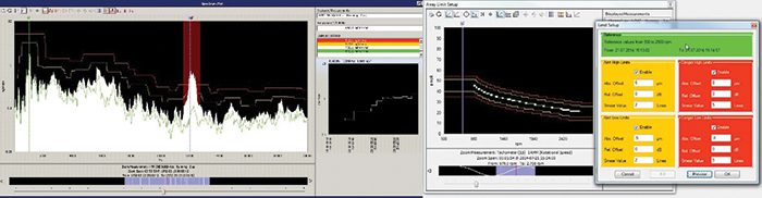
In 2010, as part of a control system upgrade, the monitoring systems on Units 2 and 4 were upgraded to the B&K Vibro VC-6000 Compass 6000 system. Both legacy systems were unique in the sense that they could monitor the special rotor dynamics of the generators (although modifications were made to the Compass 6000 system to accommodate this). This was especially important during the run-up to operating speed, where the critical speeds, resonances, and other vibration peaks could be monitored to individual alarm limits, including those close to the running speed. The alarm limits were set to individual speed bands for all the peaks for both condition monitoring and protection purposes. (Figure 5 shows how this was done in the Compass Classic system.)
 |
|
5. This example from a different power plant shows the Alarm Profiling function of the Compass Classic system during a run-up (left), and how the alert and danger alarm limits are set up on the data from a signal injector for defining the run-up speed ranges in the Compass Classic system (right). Courtesy: B&K Vibro |
As previously mentioned, only Units 1 and 4 had been operational, and in 2019 Unit 1 was to have a three-month maintenance outage, which was the ideal time to install a new monitoring system. At the time, Unit 1 still had the 25-year-old Compass Classic monitoring system installed, which was already obsolete with no spare parts available. A replacement was needed.
In 2018, an investigation was done to determine the functionally best and most cost-effective replacement for the existing system. One of the most difficult challenges for monitoring the turbo-generator units was the transient speed monitoring requirements, for both condition monitoring and protection. In addition to this, there were other requirements that had to be met, which included:
- ■ Storing data in the PI data historian.
- ■ Remote monitoring and system configuration.
Monitoring System Replacement
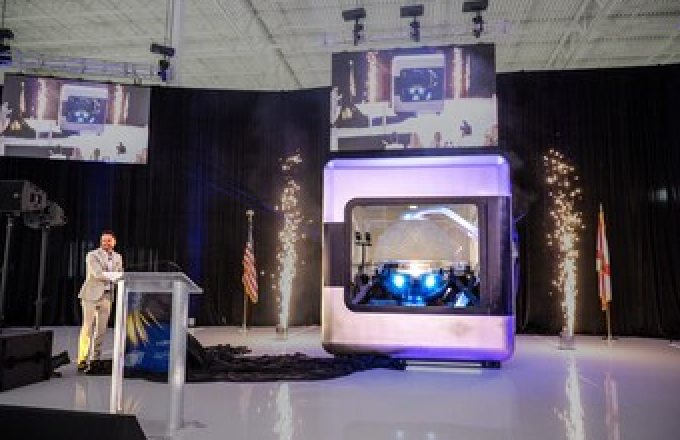
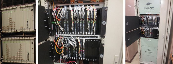
Genesis Energy looked at viable options to upgrade the Unit 1 monitoring system and there were not many systems on the market that could fulfil all the monitoring requirements. The B&K Vibro VC-8000 Setpoint system was ultimately selected to replace the legacy Compass Classic system. Setpoint was installed and later commissioned in June 2019 (Figure 6). Since it was commissioned, the Setpoint system has been providing the functionality and benefits described below.
 |
|
6. Two racks installed on Unit 1 showing the legacy Compass Classic monitoring system from 1994 (left), and the VC-8000 Setpoint installation in 2019 (center and right). Courtesy: B&K Vibro |
PI Data Historian. Setpoint already had a PI data interface, so the physical installation was both cost-effective and fast because no proprietary condition monitoring server needed to be installed. All data could be stored in PI. The existing Genesis Energy PI system consists of the local PI database server at the power station and the corporate network server. Setpoint transfers both single-point data (static data) and time waveforms (dynamic data) into the local PI server, but only static data is being transferred to the corporate network server to minimize network traffic and hard drive space. The static data, which consists of vibration amplitude and phase measurements (overall, running speed, and running speed harmonics), axial displacement, eccentricity, differential expansion, etc., is correlated and trended with process data, which includes temperature, condenser vacuum, active load, reactive load, etc. All diagnostic analysis such as orbit plots, shaft centerline plots, Bode plots, etc., is currently done in the Setpoint system, not in PI, although the dynamic data is stored in the local PI sever.
Differential Thermal Expansion. Setpoint plays an important role in monitoring the differential expansion of the steam turbine rotor in relation to the casing during startup. This is critical for the high-pressure portion because the loading sometimes has to be put on hold until the expansion evens out. Setpoint has the necessary resolution to monitor this condition accurately and can activate relays when necessary. Alert alarm relays are programmed in the distributed control system (DCS) to put a hold on loading during startup, if the differential expansion limits exceed the alert alarm limits. If the danger alarm limits are exceeded, the unit is tripped.
Balancing. This is a challenge for the generator because the second critical speed is so close to running speed. As a result, a balance weight of only 200 grams has a considerable effect when balancing the 42-ton rotor. Even the endcaps on the generator have a significant effect, as the balance can change when the endcaps settle into position after a balance weight change.
The profile alarming function of Setpoint enables the entire balancing process to be accurately and safely monitored between weight changes. (It takes approximately 24 hours between weight changes because the generator casing is hydrogen-filled.) Moreover, by monitoring small changes in the generator rotor unbalance, together with the condition of the bearings, it is possible to defer generator balancing by several months to a more favorable load period.
Transient Speed Monitoring. Setpoint can accurately monitor resonances and critical speeds during run-up and activate relays when limits are exceeded. Monitoring is done on the entire drive train, but is particularly important for the generator. Similar to the differential expansion monitoring, the alert relays for transient speed monitoring are programmed in the DCS to reduce speed if the vibration amplitude exceeds the alert limits. The unit will trip if the danger limits are exceeded. As in the case for the differential expansion, the predictive maintenance engineer is notified to do diagnostic root cause analysis, if there is an alert alarm issued or the unit is tripped.
Safe and Efficient Operation
Huntly Power Station has been providing reliable energy for more than 40 years, and the legacy monitoring solution has played an important part within the last 25 years in keeping these aging units running safely with minimal disruption. This has been no trivial task considering the high transient speed vibration peaks that have to be individually monitored to ensure a successful run-up.
The new system installed to replace the obsolete system on Unit 1 also provided enhanced transient speed monitoring, as well as specialized balancing capability, and differential thermal expansion monitoring coupled to the DCS. In addition to this, there was also PI data historian interface plus remote monitoring access and system configuration. Plans are currently underway to look at the possibility of installing Setpoint on Unit 5 (the 385-MW combined cycle unit) as the operation of this unit changes from baseload to two-shifting operation.
—Simon Hurricks is the predictive maintenance engineer with Genesis Energy. He has been with Genesis and its predecessors for 50 years, and has been based at Huntly Power Station for the last 40 years. Mike Hastings is a senior application engineer at B&K Vibro, based in Denmark, and has been with the company for 30 years. He has helped develop various machine monitoring strategies and optimization techniques.