Geothermal power is increasingly cited as a renewable energy resource with a vast potential to make the world’s electricity supply more sustainable. Many areas utilizing geothermal are located where the heat used to generate the power occurs naturally, existing underground as pockets of steam or hot water. In other areas, the resource needs to be “enhanced” with injected water to create steam.
The world’s first geothermal power station was built in Larderello, Italy, more than 100 years ago. The plant has been expanded over the years, and today consists of nearly three dozen plants, with generation capacity of about 800 MW. The Larderello complex, operated by Enel Green Power, has helped Italy become the sixth-largest producer of geothermal energy in the world, as the technology forms nearly 2% of Italy’s energy mix.
 |
|
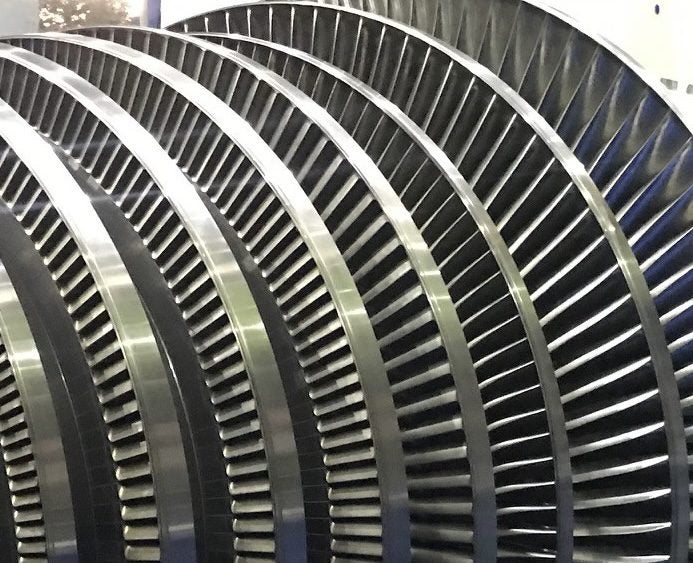
1. The Sonoma geothermal plant is part of The Geysers, the world’s largest geothermal field, located north of San Francisco in the Mayacamas Mountains region of California. The Sonoma plant, a dry steam facility, was commissioned in 1983. Source: Creative Commons / Stepheng3 |
The current technologies in use at geothermal facilities include dry steam power stations (Figure 1), flash steam power stations, and binary cycle power stations, along with enhanced geothermal systems. The dry steam power station directly uses geothermal steam to run the turbines. As the turbine rotates, it powers a generator, which then produces electricity and adds to the power field. The steam is then passed through a condenser, where it is cooled and sent back into deep wells where it can be reheated and produced again.
The flash steam power station, the most common type of geothermal plant, uses flashed steam to drive turbines. Heat is pulled from deep within the earth, with high-pressure hot water fed into lower-pressure tanks, creating flash. The leftover water (condensed steam) may be injected back into the reservoir.
In a binary cycle power station, the geothermal heat can be low. It is passed by a secondary fluid with a lower boiling point than water to create a secondary fluid, used to create the flash to drive the turbine.
An enhanced geothermal system (EGS) is a manmade reservoir, created where there is heat in the rock, but not enough natural permeability or fluid saturation. In an EGS, fluid is injected into the subsurface under controlled conditions, which cause pre-existing fractures to open, creating permeability.
In each of these systems, the underground heat generated is the energy resource, which is then sent to a turbine, which in turn powers the generator to produce electricity. The steam passes through a stop and emergency valve, which is regulated by a hydraulic mechanism. It is then passed onto throttle valves, which control the flow of steam to the nozzle chamber. The control action is governed by an actuator through an electronic governor. The speed of the rotor is captured by a magnetic pickup unit (probe), and then transmitted to the governor.
The steam nozzles located in the nozzle chest serve as an inlet to the turbine where the potential energy is converted to kinetic energy. This steam is then directed toward the turbine blades, which turns the rotor. Steam is fed through one or several convergent-divergent nozzles where pressure drop occurs in the nozzles.
The torque generated by this rotary motion is transferred via a coupling, which is either connected to a step-down gearbox, or directly connected to the generator depending on the speed at the output. This torque is then transmitted to the generator to generate the required electricity as per load requirement.
Lifecycle Issues
Although geothermal power plant stations are more environmentally friendly than other energy stations, the steam contains large quantities of chloride, methane, sulfate, hydrogen sulfide, and other corrosive chemicals, which tend to erode the surfaces of the internal equipment, including specifically the rotor, thus reducing the lifecycle. This is a phenomenon experienced across most geothermal plants.
The most common issues faced by geothermal turbines are the frequent erosion of the blades, and cavity formation due to impurities in the steam. This leads to reduced efficiency, with blade failures resulting in unexpected breakdowns.
 |
|
2. This image shows a fully re-bladed spare rotor with upgraded design before high-speed balancing. Most geothermal power plant operators will keep spare turbine equipment in their inventory, although carrying excess inventory can contribute to higher operating costs. Courtesy: Triveni Turbines |
To reduce the downtime caused by unexpected breakdowns, most operators of geothermal plants often carry spare turbine internals, ranging from moving and stationary blades to a fully bladed rotor (Figure 2). This is a capital-intensive scheme, increasing the cost of operating a geothermal plant due to the higher cost of carrying excess inventory.
This cost, though, can be reduced by improvements to the plant’s equipment, including redesigning internals within the existing housing, and without any civil modification. There are many benefits to the redesign of internal components, including:
■ Improvement in efficiency.
■ Reduced operational expenditure.
■ No change in the civil foundation.
■ Existing turbine housing being reused.
■ Life extension of asset.
■ Increase in span between overhauls.
■ Reduced inventory.
Case Study
A case study of the redesign of internal equipment for a geothermal plant provides examples of the benefits. A major customer in the geothermal sector was facing issues of erosion and corrosion, which was leading to below-par performance of the turbine. The turbine, a direct-drive type, was designed for output of 17 MW, with single-cylinder, single-flow backpressure.
The operator did its due diligence, looking at possible options to source the rotor, prior to partnering with India-based Triveni Turbines to remanufacture the rotors. Triveni is an original equipment manufacturer, and among the world’s largest makers of steam turbines for power generation.
The customer listed three major challenges it faced at its geothermal operation. They were:
■ Frequent erosion in the riveted tenon of the blades.
■ Formation of cavity by erosions at high-pressure gland areas due to impurities in the steam.
■ A need to improve the rotor material to extend the life of the rotor.
Based on the inputs, a number of iterations were carried out and design changes were made during the manufacturing of the new rotor. The existing rotor, which had a riveted shroud design, could not be de-bladed. That was because the blades would have to be replaced once de-blading activity was completed, which would have resulted in extended downtime for the customer. A de-blading would have enabled Triveni’s designers to understand the existing root design. However, the specialists understood the customer’s requirement and captured only minimal information including the outside geometry of the rotor and inside envelope of the casing.
With the design team’s immense experience of working on multiple, similar situations, and based on a study of various root designs, the rotor was redesigned with new and upgraded roots. The rotor data that was captured had to be 3D-modeled to conduct a preliminary design review to select the suitable root designs. Upon completion, a detailed engineering evaluation was carried out by a thermo-structural study, with a goal of limiting stresses within the allowable value. This was followed by frequency analysis to understand the dynamic stress effect on the blades. A careful review was also done to ensure the locking blade integrity with the new design was sustained.
Additionally, several design modifications were carried out. The existing riveted shroud design was causing erosion due to the geothermal environment. The existing design was modified to a new, improved design, to remove the possibility of erosion at the riveted area.
 |
|
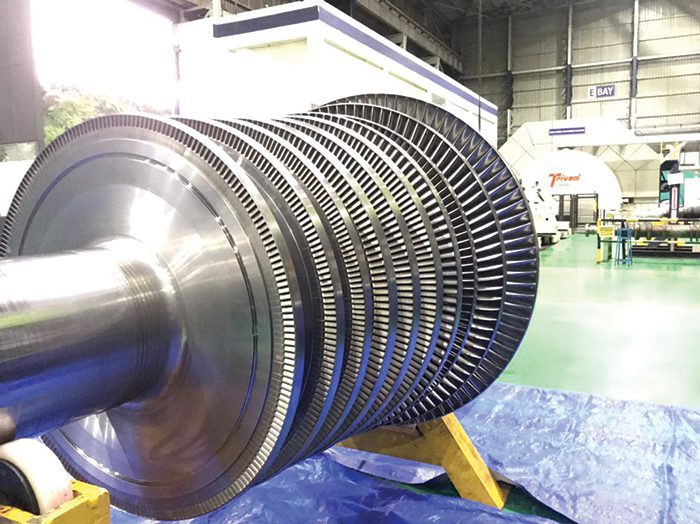
3. This image shows a bladed rotor ready for packing after high-speed balancing and application of a preservative. Upgraded materials and coating procedures can ensure higher resistance to corrosion and erosion, significantly improving the life of the rotor. A turbine redesign also can help reduce stress on the surface and other areas of the rotor. Courtesy: Triveni Turbines |
The new rotor (Figure 3) was upgraded to a material with higher resistance to corrosion and erosion, allowing for better creep resistance. To ensure that the material of the rotor did not impact the bearings or any other components, Triveni carried out a coating procedure on the journal area. This significantly improves the life of rotors.
Redesign to Reduce Stress
The redesign included a special process to reduce the stress induced on the surface of the rotor disc, blade root, and transition fillet to increase fatigue life. This action induces residual compressive stress on the surface, which delays the appearance of cracks and enhances the lifecycle.
These value-added additions were done to ensure the customer would receive an extended lifecycle for the turbine, while also improving the availability and efficiency of the plant. The rotor was subjected to high-speed balancing, a process by which the mass distribution about the spin axis is checked and corrected to ensure the bearing forces and vibrations of the shaft corresponding to the frequency are within specified limits. This process eliminates the vibrations caused by imbalance and helps ensure the safety of rotating equipment.
The new rotor was swapped with the old one and commissioned with vibration in an acceptable range on the first run. This high level of performance allowed the customer to immediately commence commercial operations.
—Arun Mote is executive director and CEO at Triveni Turbines.