Restraining Torsional Vibration
All rotating equipment power trains found in a power plant have some amount of vibration, usually caused by mechanical unbalance of the rotating system, shaft misalignment, or weakness in the bearing support. Characteristic vibration is also experienced in one or more of four modes: sideways, horizontal, axial, or torsional.
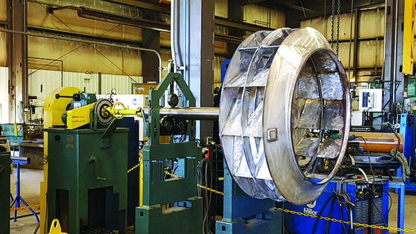
The first three vibration levels are typically measured by either displacement, velocity (the speed of the motion), or acceleration. Torsional modes describe the twisting and untwisting of the power train shaft and are the most difficult vibration problem for which to identify the vibration’s source and solution (Figure 1).
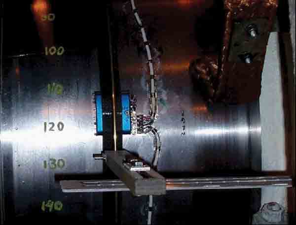
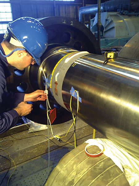
1. Twist equal to strain. The typical method of measuring torsional vibration in a power train shaft is to use strain gauges. Courtesy: GE Energy
Torsional Vibration Is Difficult to Control
Each mode of vibration can be magnified by an exciting force (usually the rotating velocity of the power train or a multiple of that velocity) that resonates with the natural frequency of the support structure, which includes the bearing supports or support structure defect. In power trains with a generator, an exciting force has even been identified as electromagnetic torque caused by a bad air gap.
The torsional resonance frequency of any power train is a strong function of the component dimensions (such as shaft diameter and length) and material properties. Selecting these design parameters also defines the component stiffness, inertia, and other important characteristics important to a well-behaved power train.
Normally, the exciting frequency can’t be changed (it’s a function of the operating frequency of normally 50 Hz or 60 Hz), but the natural response frequency of the structure or power train can be altered by either stiffening (which raises the frequency) or by making it more flexible (which lowers the frequency). Unfortunately, those options are not available for resolving torsional resonance problems; changing shaft stiffness normally requires changing the diameter or length of the shaft.
High-inertia power trains are very susceptible to torsional vibration. High-inertia power trains don’t want to shift their angular position in the bearing, but the oscillating torque placed on the shaft by the torsional vibration does. This rapid flexing of the power train causes high fatigue cyclic stresses that can result in a mechanical failure, many times without warning. Torsional resonance with the oscillating frequency will accelerate the time to failure.
The torsional dynamics of a turbine-generator power train have very little damping as compared to the lateral dynamics. This factor amplifies the impact of a stimulus or exciting force in line with a natural frequency; however, a response will not be seen unless the two are very nearly equal. Torsional stimuli are seen at one and two times the electrical line frequency, as it generally arises from continuous, low-level, harmonic excitation and can also (rarely) be seen as high-level, transient excitation. Both low-level and high-level stimuli can result in catastrophic failure, such as liberating rotating components (for example, last-stage turbine buckets). This component liberation causes very large lateral unbalance that can further damage the turbine-generator set.
New production turbine-generator trains have system dynamics designed with the latest analysis tools to avoid torsional stimulus frequencies. However, in the past this capability was not available and some power trains were designed with torsional natural frequencies very near twice (2x) line frequency. These units may have operated for many years without incident; nevertheless, the risk would be that any modifications to the rotor train could shift a close natural frequency right onto a stimulus frequency.
There are a variety of aftermarket modifications that could significantly affect torsional dynamics, including rotating exciter to static exciter conversion, replacement generator or turbine, replacement rotor or field, replacement buckets, non-OEM replacement components, and many others.
Torsional Testing Required
Because of the risk of catastrophic failure, any modifications that could affect power train modal frequencies should be preceded by a full dynamics study. Such a study requires detailed information about each component in the rotor train, which can be difficult to obtain if different suppliers manufactured the hardware. If the analysis results predict the modifications will move a natural frequency near 2x the line frequency, or that the current configuration has a mode near 2x line frequency torsional, testing of the train will be required. This testing will validate the rotor dynamics model and help identify ways to mitigate risk. A post-outage test is also recommended to validate predictions and effectiveness of corrective actions.
If testing has confirmed that a unit has a high risk of experiencing a torsional resonance due to an upgrade or modification, there are several options to mitigate that risk. The modification could be canceled, continuous torsional monitoring could be employed, or the train could be dynamically detuned.
Detuning the Old Way
The traditional method to detune the natural frequencies of a high-risk train is to directly modify the torsional stiffness or inertia of the critical component in the train. Modifying a rotor torsional frequency through directly adding or removing inertia generally requires significant component alteration. Such changes can also affect lateral dynamics and are generally not readily adjustable.
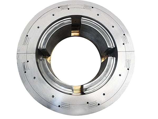
One technique commonly employed is the addition or removal of large, high-strength inertial rings over the coupling flanges. These changes can approach design limits and existing available space. Installing and/or removing mass rings typically would require decoupling from the prime mover and pulling the rotor back to allow the installation or removal of enclosure rings over the coupling. These are large, high-strength, expensive rings.
If this method does not provide a sufficient shift in the natural frequency, then the rotor, or components in the coupling, would need to be machined to remove stiffness or inertia, depending on the situation. This approach requires complete removal of the field and machining on site, if the capability were available, or sending it to a service shop. Each of these steps would add significant expense to the solution. Furthermore, they could cause an extension in the outage if a lot of work were required.
Torsional Dynamic Tuner Now Available
A new method developed by GE for altering power train torsional modes is to employ a torsional dynamic tuner. The method has been validated through testing and has been successfully implemented at a power plant.
The torsional dynamic tuner can detune a rotor in a power train, typically the first- or second-generator rotor twist mode, which is undesirably close to a 2x line frequency excitation. By adding inertia to the end of the generator shaft, the mode of the overhung shaft section beyond the main rotor body is tuned to match the generator rotor body twist mode. The overhung shaft will behave as an undamped dynamic torsional vibration absorber. Once the two sections are tuned to have identical torsional natural frequencies, any forces exerted on the rotor at the frequency of interest will induce a response force from the overhung shaft back into the rotor 180 degrees out of phase of the exciting force, significantly diminishing the response amplitude at this frequency.
Furthermore, the natural frequency of each shaft section will split away from this point. The magnitude of this split will depend on the mass ratio between the two sections. External torsional forces induced into a power train generally come from either the flux load across the air gap on the generator or steam or gas loads on the prime mover. Torsional loads across the air gap on the generator typically occur at twice line frequency, so noise in the electrical grid can cause fluctuating tortional loads on the power train.
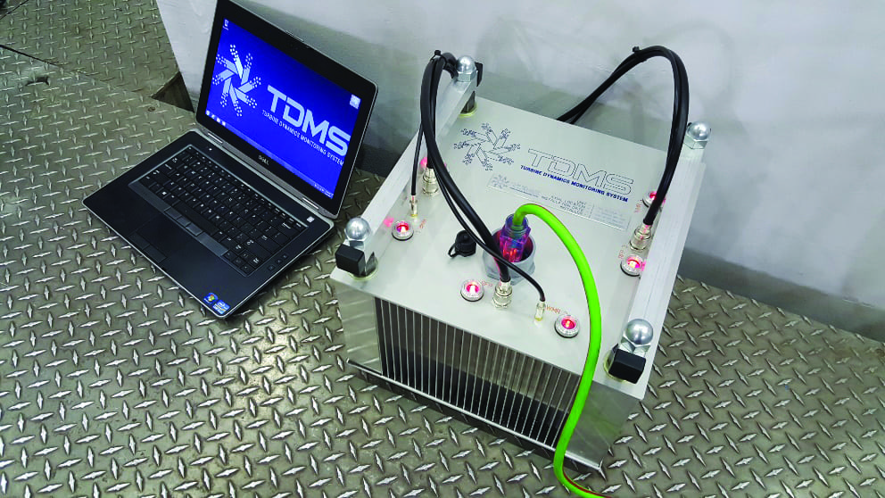
The key to this new method is the simplicity and low impact of the modifications that nonetheless deliver the desired result. Most overhung twist modes lie above the critical frequency of 2x line frequency; therefore, by adding a small amount of inertia via a bolted on wheel at the end of the overhung shaft, the entire inertia of the overhung shaft can be used in altering the generator twist mode. Furthermore, because this is a low-impact change and the work can be done while the unit is still fully assembled, there is opportunity to verify that results are acceptable and make further adjustments as needed. Torsional testing, using torque rings, can be used as a means to both identify problematic rotor frequencies and to validate effects of the dynamic absorber, without changing the torsional or lateral dynamics of the power train.
Consumer’s Energy Campbell Station Success Story
Consumer’s Energy J.H. Campbell Generating Complex recently completed an aftermarket upgrade to the excitation system on the 800-MW Unit 3 that unexpectedly affected the power train dynamics. Following the alteration, testing confirmed there was a generator torsional mode very near the critical 2x grid frequency (Figure 2). In fact, the unit passed through 120 Hz during operation (from low load to full load). The risk of equipment damage and failure was too high to continue operation in this condition, so various alternatives were explored.
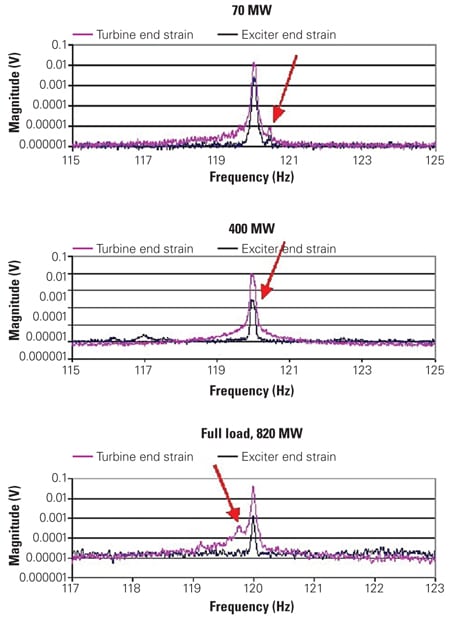
2. Pre-tuning results. Testing of the generator end of the power train confirmed that there was a torsional mode at 2x the operating frequency (120 Hz or 3,600 rpm) under all operating conditions (see red arrows). Continued operation under these conditions would soon cause mechanical damage of the power train. Source: GE Energy
The usual method of coupling inertial rings could not provide sufficient margin from the stimulus frequency to meet standard separation margins so this option was discarded.
The Campbell staff contacted GE to explore other technical options. GE engineers used this opportunity to develop, test, and install the first full-scale torsional dynamic tuner in the spring of 2007 (Figure 3). With minimal alterations and down time (<300 pounds of hardware installed at the free end of the shaft), the torsional dynamic tuner achieved over 150% of recommended frequency margin under all plant operating conditions, including start-up (Figure 4).
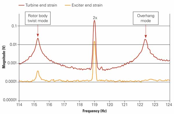
3. Post-tuning results. After using the first full-scale torsional dynamic tuner, GE engineers were able to determine the amount of weight that should be added to the generator-exciter end of the power train shaft to achieve over 150% of the recommended frequency margin. Source: GE Energy
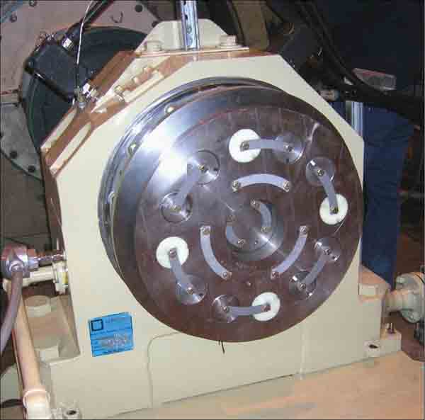
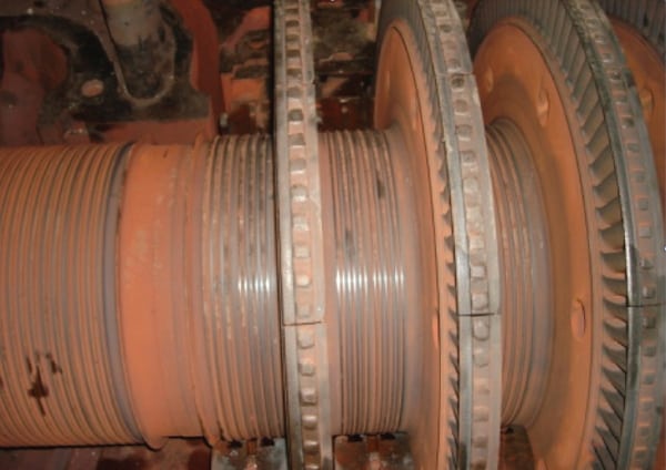
4. Tuner hardware. About 300 pounds of weight was added to the generator shaft end to achieve the required torsional frequency margin. Courtesy: GE Energy
— Contributed by Alexander G. Beckford (alexander.beckford@ge.com), a principal engineer, and Benjamin A. Mancuso (benjamin.mancuso@ge.com), an engineer, with the Generator Services Engineering division of GE Energy.