Advanced computer design tools have merged with high-definition laser camera scan data to produce integrated images that are particularly useful for outage and maintenance planning. A 3-D tool that enables a project team to perform virtual equipment removal or installation is essential when each extra day of actual labor adds millions of dollars to outage costs. Here’s an example of how it works.
Planning for a major maintenance outage usually begins one to two years in advance of the work when major equipment overhaul or replacement is involved. A good example is replacement of a steam generator in a typical pressurized water reactor plant. An essential part of that outage planning process will include determining the crane design required to lift the new steam generator into place and skid it into the containment vessel. The real challenge comes when the old vessel must be cut out, interferences removed, and proper rigging points identified. These aren’t chores that can be handled on the fly, especially given that construction (and deconstruction) process planning and close craft and equipment coordination are vital as outage intervals continue to compress.
The design engineer must have accurate plant documentation showing the location of every pipe and conduit so that the least-invasive path can be selected for large equipment removal. However, chances are your plant was designed in an era when only 2-D computer aided design (CAD) design tools were available. Although it’s unlikely, let’s hope your paper drawings were accurately updated after construction to show the plant’s as-built configuration. Chances are that after a few years, your plant drawing database contains some inaccuracies.
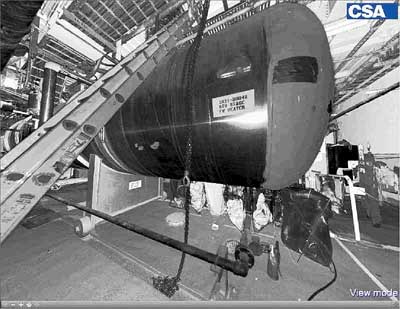
One technology that solves the plant design documentation dilemma is laser scanning. Laser scanning is a very effective and efficient approach for developing very precise digital as-built documentation of even the smallest details found in a power plant, especially those areas that are difficult to access during operation or where access is available for only short periods. In fact, you can measure distances and other key dimensional data directly from a digital scan (Figure 1).
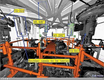
1. Digital diagrams. A laser scan of a typical equipment room can be supplemented with scaffolding, dimensional data, and components to be removed, thereby serving as part of a comprehensive overhaul or replacement planning tool. Source: CSA Inc.
Laser scanning also provides a dimensionally accurate representation of the plant and all its equipment as well as a photographic quality visual representation. The laser scan database can be integrated with a variety of plant design applications to provide comprehensive facility management support.
In fact, a laser scan 3-D database can be combined with the 3-D CAD tools now becoming more common to develop a comprehensive representation of a facility. This virtual view of a plant can now be used to explore alternative equipment removal evolutions, scaffolding management, or rigging sequence planning and training. It can even be integrated with other radiation-monitoring technologies. Also, for a nuclear plant planning an outage, complete equipment removal and replacement simulations can be performed to identify construction and access problems when they are easily resolved, rather than when a hole is open in the containment building.
There are other less-obvious uses of laser scanning for new plant construction. For example, scanning might be used to document areas and components that would be closed or inaccessible after completion of construction. It could also document construction tolerances, design, and installation of components that are traditionally field-routed (such as small-diameter piping, tubing, conduit, and the like). You could even scan a completed facility to create comprehensive as-built documentation for use by plant operation and maintenance staff during commercial operation.
Close integration
Previously, 3-D modeling was used extensively to support the planning and design of major equipment removal or replacement projects. The difficulty with 3-D modeling alone was that it required almost perfect design documentation of the removal path, and creation of a 3-D model was relatively expensive and time-consuming.
In contrast, 3-D laser scanning represents a considerable improvement by reducing costs and eliminating the need for stacks of plant drawings and equipment specifications. Laser scanning is a quick mechanism for capturing a comprehensive representation of the area in question and the areas affected by the removal and reinstallation of an equipment item. Its documentation also provides a very effective representation of the space that can be well-integrated with many 3-D CAD systems.
The scanning plan
Below are the basic steps used to create a 3-D laser scan of typical power plant equipment room for a feedwater heater replacement project.
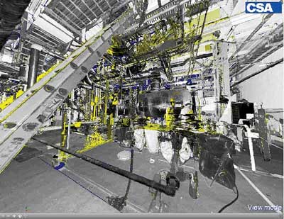
Laser scan the expected removal path. Laser scanning is planned according to potential rigging path areas. It is important to cover areas affected both by equipment movement and by temporary rigging structures. A plan view of an equipment floor shows the scanner locations for the heater removal site as green boxes (Figure 2).

2. Location planning. The location plan of an equipment removal area with scanner locations shown as green squares. Source: CSA Inc.
High-resolution, 360-degree laser scanners are then used to collect the digital plant data. These scanners provide a very good dimensional representation as well as a very good visual representation of the area. The scans are typically made during a planned outage if the area is not accessible during normal plant operation.
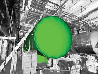
Create the laser scan 3-D database. The laser scans are first registered to the plant coordinate system. The registration also synchronizes the 3-D representation to any 3-D models created to support this application. The scan database is available in a visual 3-D format to allow the user to measure any locations or distances within the scanned space. The scanned database is also available in 3-D CAD (surface model) format representing scanned surfaces. This format can be transferred to any CAD system as a background for design and is also used for interference checking (Figure 3).

3. Paint your surface. An example of a surface CAD format generated from a series of laser scans. Source: CSA Inc.
Model in 3-D the equipment to be removed. A 3-D model of the equipment to be removed is prepared from the vendor drawings. The disadvantage is that the equipment to be removed may have extended parts, which may not be obvious from the installed configuration. The equipment 3-D model can have tolerances added to verify possible "close call" interferences. The equipment to be removed is then verified against the scans and any necessary corrections and adjustments are made. If the new equipment is different from that being replaced, a 3-D model of the new equipment is made for the equipment replacement simulation. A tolerance can also be added to the new equipment model.
Model in 3-D the rigging equipment and supporting structures. A 3-D model of the rigging equipment and supporting structures is prepared and added to the overall database. This 3-D model can be merged within the scans and verified for the intended use. (Figure 1 also shows a good example of how a rigging plan can be added to a equipment drawing.)
Create the removal path and simulation sequence. Determine the removal path for equipment removal and replacement. Several alternative paths can be identified to verify possible removal options. The equipment can be rotated and lifted as necessary over the removal path (Figure 4).

4. Moving day. A CAD model of the equipment to be moved can be superimposed on a laser scan 3-D model showing the removal path. Source: CSA Inc.
Documentation of the equipment translation/rotation sequence is stored in a special motion-simulation file. This file is used to move the equipment through this path. The result is a 3-D version of the equipment translation/rotation through the plant. The simulation may also include moving of the rigging equipment as necessary.
Remove the old equipment from the scan database. Equipment to be removed can be eliminated from the 3-D model, and then applicable scans are reprocessed. Figure 5 provides an example of where a vessel was eliminated from the 3-D scan model of the original plant equipment.
5. Delete from memory. Equipment originally included in the 3-D scans (top) can be electronically “erased” from the CAD file (bottom). Source: CSA Inc.
Merge the equipment removal sequence within the scans. The equipment to be removed is replaced within scans by the 3-D version of the equipment (Figure 6).
6. Add from CAD. The model of the moved equipment is merged with multiple scans within the plant along the removal route. Source: CSA Inc.
The next step is to merge the simulated equipment path within scans and generate a new set of scans that represent the merged equipment simulation sequence. These scans can be reviewed within PanoMap — a laser scan 3-D viewer, part of the Laser Scan Space Manager (LSSM), which is a module of this case study plant’s overall plant configuration management system — or Plant/CMS, which provides intelligent 3-D technology for large-scale plants. Within Plant/CMS, the removal path sequence can be reviewed and adjustments to the path can be made. Based on these adjustments, some of the steps will need to be reprocessed.
Using PanoMap, the user can review the equipment’s movement process through all the scans. Notes, labels, and instructions also can be placed in individual scan views. Additionally, any electronic drawings, procedures, photographs, or documents can be hyperlinked to the scans (Figure 7).
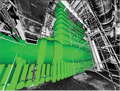
7. Model movement. When the moved equipment models are merged, a complete view of the path can be displayed. Source: CSA Inc.
Check for interference. The laser scans within the removal sequence are reprocessed to show interferences between the moved equipment and the plant background. Interferences are shown in red within the scans. The user can review these scans and adjust the removal sequence or plan for the removal of interfering components. Scans with marked interferences can be reviewed with the 3-D solid representation of the equipment throughout its trajectory or path (Figure 8).
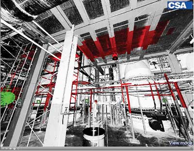
8. Get out of my way. Interferences checks are also automatically performed as part of an integrated removal sequence. Areas shown in red are interferences. Source: CSA Inc.
Create the removal sequence movie. LSSM/PanoMap together with Plant/CMS can be used to create a simulation movie of the removal process. The simulation movie is controlled by two trajectories: the equipment removal sequence, including the movement of rigging equipment, and defined user viewing locations.
These two trajectories are then merged to provide the desired simulation effect. The equipment rigging sequence is controlled and manipulated within Plant/CMS. The user can control the density of the generated steps. Viewing is based on scanner location positions, because this provides a 100% unambiguous view of the scan coverage.
The last step is to output a movie in.AVI format. Examples of these videos can be viewed on our web site (www.csaatl.com).
—Amadeus M. Burger (amadeus@csaatl.com) is president of CSA Inc., which specializes in developing three-dimensional computer databases as a tool for facility lifecycle management.