Renewable energy, though still accounting for a comparatively small portion of overall supply, generates a larger portion of the world’s electricity each year. Combining many of the available solar energy conversion technologies with conventional fossil-fueled technologies could reduce fuel costs while simultaneously helping utilities that are struggling to meet their renewable portfolio goals.
Renewable energy technologies face two near-term deployment hurdles when compared to traditional forms of power generation. First, their initial capital cost typically is much higher on a dollars per installed kilowatt basis, and that first cost is only partially compensated for by lower operation and maintenance (O&M) and fuel costs. This is especially true when today’s higher project costs are compared to those of conventionally fueled projects installed a decade or more ago.
The other important issue is dispatchability. There are few renewable options available to a dispatcher on a still, overcast day when the public demands electricity. Fast-acting gas turbines will have the advantage over renewable energy supplies when instantaneous matching of supply with demand is required — at least until some form of energy storage mitigates the intermittent nature of renewable energy sources. However, progress to commercialize large-scale energy storage technologies has been evolutionary, rather than revolutionary, and many technical and cost issues are yet to be resolved.
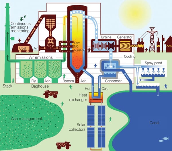
So why not take the best of both power generation technologies and integrate renewable power sources, such as concentrating solar thermal power (CSP), with existing or new combined cycles or conventional steam plants? The resulting hybrid plant will increase power or reduce fossil fuel consumption (justifying the high capital costs), mitigate the intermittent nature of most renewable technologies, remain dispatchable, and help many utilities with large fossil plant investments meet their renewable energy mandates.
The Best of Both Worlds
Conventional gas-fired combined-cycle plants represent perhaps 40% of the installed power generation resources in the U.S., yet they produce much less than half of the electricity sold. These plants uniformly have very high thermal efficiency and the smallest carbon footprint of any fossil-fueled generation technology, but the steeply rising cost of natural gas has pushed these plants into unfamiliar territory, where they operate as cycling rather than baseload plants. In other words, a typical combined-cycle plant is suitable for including in an integrated solar combined cycle (ISCC) configuration, where the solar energy portion of the plant can provide additional power at peak demand. We explore the solar power options for conventional steam plants later in this article.
The conversion of a combined-cycle plant to an ISCC begins with adding an additional source of heat, such as solar energy, to reduce natural gas consumption and thereby improve overall plant efficiency.
There are other advantages of an ISCC, even when compared with standalone CSP-inspired plant designs. (See POWER, December 2007 for a review of the Nevada Solar One CSP plant.) For example, the ISCC uses existing components (such as steam generators, steam turbine, and condensing system) that reduce the installation cost of a typical CSP system. Also, the potential for generation is increased because the steam turbine would be already synchronized to the grid when the solar energy contribution is added, thus avoiding lost generation during start-up. Another key advantage is gained during rising ambient temperatures, when gas turbine performance steadily drops. Operation of the solar energy portion of the ISCC compensates for that loss in efficiency and electricity production and improves the plant’s part-load performance.
Combining solar energy with conventional coal-fired plants is also possible in regions with reasonably good solar conditions. For these plants, where the steam pressures and temperatures are higher than for ISCC, the type of solar conversion technology used (Fresnel, parabolic trough, or tower) will dictate how solar is integrated into the plant.
Finally, don’t discount the possibility of hybridizing conventional plants with other, even multiple, forms of renewable energy such as biomass and wind. Our discussion of ISCC illustrates a single development path electric utilities could follow to efficiently and inexpensively bring multiple forms of renewable energy online in short order. Many other options are available, depending on the design of existing plants and their location particulars.
CSP: Steaming with Solar
Concentrated sunlight has performed useful work for humans for many years. There is one notable example of Auguste Mouchout, a French inventor, who in 1866 successfully powered a steam engine with sunlight, making him the first known person to construct a concentrating solar-powered mechanical device.
Today, a typical CSP system requires several unique components to produce electricity: a concentrator, a receiver, a heat transfer system, and a power conversion device. There are several ways to combine these components to produce a useful solar energy – powered, electricity-producing plant, although the key enabling technology is the collector. Descriptions of the currently available options follow. All of the available CSP technologies require direct sunlight to function and are of limited use in locations with significant cloud cover.
Parabolic Trough Collector. The parabolic trough is considered the most proven technology of all the CSP options. More than 350 MW of electric power have been installed using this technology since the 1980s.
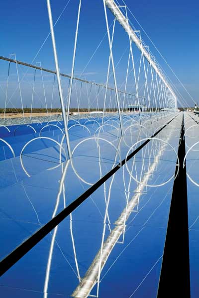
The parabolic trough design begins with a very large curved mirror. The parabolic shape is designed to concentrate solar energy and reflect it onto a single point. The mirror position follows the sun’s movement in the sky, using a motorized device. The cylindrical parabolic reflector is traditionally made of thick glass silver mirrors (4 to 5 mm, or 0.15 to 0.2 inches), but thin glass, plastic films, and other polished metals are also used.
A receiver tube located at the focal point of the parabolic mirror collects the concentrated solar heat energy. This metal tube uses special coatings to maximize energy absorption and minimize heat losses. Flowing inside the tube is a conventional heat transfer fluid (HTF), which absorbs the thermal energy from the concentrated sunlight. Another glass tube, kept under a vacuum to further reduce the heat losses, envelops the receiver tube.
Several receivers connect to a circulating HTF loop, which enables the enlargement of the system. Many loops combine to form a plant that can now leverage its scale to produce economical power. About 4 to 5 acres will generate 1 MW of energy.
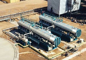
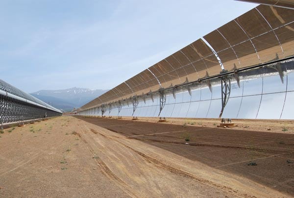
The hot HTF produced by the combined loops, serving as the "fuel" source, next enters a steam generator to produce superheated steam. The cooled HTF returns to the CSP modules to be heated again in a closed loop. The generated steam is used to produce power in a conventional steam-bottoming plant. The maximum HTF temperature is ~395C (743F), mainly due to the operational limitation of the synthetic heat transfer fluid (Figure 1).
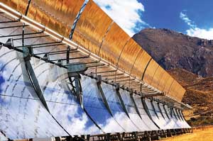
1. Solar trough technology. Parabolic reflectors focus the sun’s energy on a glass tube filled with a heat transfer fluid in this demonstration plant at the Plataforma Solar de Almería in southern Spain. The heat transfer fluid is used as “fuel” to produce steam that can then produce electricity in a standard steam-bottoming cycle. Courtesy: DLR
The two main disadvantages of trough technology are the relatively low maximum HTF operating temperature, which limits the thermal efficiency of the steam turbine system, and the added complexity of the binary fluid steam generator. However, trough technology is well understood and has a good operations record on a relatively large scale. This experience base may give trough designs an advantage over other, more interesting CSP technologies that are still in their infancy.
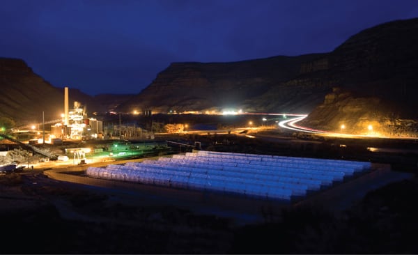
Fresnel Collector. The Fresnel solar collector is a line-focus system similar to the parabolic trough, although it uses an array of Fresnel reflectors to concentrate the sun’s energy on a series of receivers. Normally, single-axis tracking flat mirrors fixed to a steel structure are used. Several frames are connected together to form a module, and the modules form a long row up to 450 meters (1,470 feet) long (Figure 2).
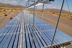
2. Fresnel lens technology. Fresnel reflectors concentrate the sun’s energy on a receiver at the Plataforma Solar de Almería, Spain.Courtesy: DLR
The receiver consists of one or more tubes located above the mirrors at a predetermined height. The metal tubes have an absorbent coating very similar to that used in trough technology to increase heat absorption. Inside the tubes flows water or a mixture of water and about 70% quality steam. At the exit of the tubes, water and steam are separated, and saturated steam is produced either for process use or to generate electricity using a conventional Rankine cycle power block.
The Fresnel collector approach does have several technical advantages over the more familiar parabolic lens CSP technology: It can generate steam directly, without the need for an intermediate HTF or binary steam cycle; the optical precision required of the Fresnel lens is less than for a parabolic lens; and the system more easily lends itself to factory production, which means less field construction is required.
However, Fresnel technology is much less mature, and the lower steam temperatures keep the steam turbine cycle efficiency low. In addition, the lower optical efficiency of the Fresnel receiver increases heat losses due to the absence of insulation around the receiver tubes.
Solar Power Tower. In this concept a boiler or gas turbine on top of a tall tower receives concentrated solar radiation from a field of heliostats, which are two-axis tracking mirrors (Figure 3). The heat transfer media could be water or steam, molten salts, or compressed air, although water is usually selected. The heated water temperature — close to 545C (1,013F) — is higher than in any other line-focus system.
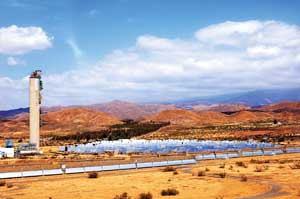
3. Power tower technology. German Aerospace Center (DLR) scientists were ableto demonstrate a hybrid solar-powered gas turbine system (230 kW) at Plataforma Solar de Almería. The sun’s energy is focused on a point at the top of the tower to produce heat energythat may be used to generate steam or to heat air. This plant uses three receivers, connected in series, to gradually heat the compressor air of a 250-kW gas turbine to 800C (1,472F). Courtesy: DLR/Steur
The power tower can be connected to a molten salt storage system, thus allowing the system to operate for periods of low or no incident solar energy. The main advantage of this technology is its ability to provide high-temperature superheated steam. The design does require very accurate alignment with solar rays, plus heliostat controls, to avoid potential damage to the receiver on top of the tower.
Note that each of these three CSP technologies operates at different working fluid temperatures (Table 1). This is a key point: Which CSP technology is selected for a solar hybrid plant, be it a gas turbine combined cycle or a conventional steam power plant, will likely be determined based on the temperature of the generated steam and how that temperature matches the fossil fuel – generated steam uses that can be replaced.
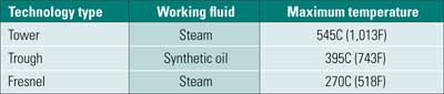
Table 1. Summary of concentrated solar technologies. Source: Bechtel Power Corp.
Options for Integrating Solar with Combined Cycles
Discussions concerning integrated solar combined-cycle plants have been going on for many years, and several plants have been proposed, are in development, or are under construction (Table 2). For our discussion, we select a hypothetical new combined-cycle in a 2 x 1 arrangement using F-Class gas turbines, unfired three-pressure, reheat heat-recovery steam generators (HRSGs), a reheat steam turbine with throttle conditions of 13.1 MPa (1,900 psia)/566C (1,050F) and reheat temperature of 566C, and an air-cooled condenser.
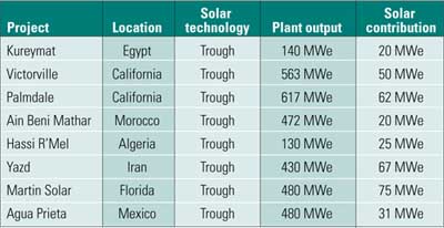
Table 2. Partial list of proposed integrated solar combined-cycle plants.Source: Bechtel Power Corp.
Determining how best to integrate steam generated by a CSP technology with a combined cycle is obviously highly dependent upon the steam conditions possible from the different CSP technologies. You will recall that all the power generated in the steam cycle of a combined cycle is "free" from a fuel perspective. That is, steam cycle power is produced without burning any additional fuel (all steam cycle power is a function of the energy remaining in the gas turbine exhaust gases). Replacing the free energy in the gas turbine exhaust gases with energy from solar power to generate steam isn’t productive. The design objective must be to optimize both sources of energy.
Solar Road Map
Determining how to technically integrate each of these three solar technologies into the hypothetical combined-cycle plant (or a conventional steam plant) is the first step in the design process. A close second step is calculating overall plant economics. To simplify the technical analysis, we have categorized each technology based on fluid temperature capability (high temperature: >500C (932F); medium temperature: 400C; and low temperature: 250C to 300C). We begin with medium-temperature technology, as it is the most proven of the three.
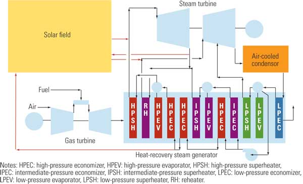
Medium-Temperature CSP. The most common medium-temperature solar technology is the parabolic trough. State-of-the-art parabolic trough systems produce up to approximately 380C (716F) saturated steam. That steam is then mixed with the saturated steam generated in the HRSG high-pressure (HP) drum (Figure 4).
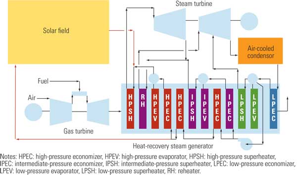
4. Medium temperature integrated solar combined cycle. Source: Bechtel Power
Integrating HP saturated steam into an HRSG is very common in integrated gasification combined-cycle (IGCC) plant designs; heating feedwater is an example. An engineering company familiar with the integration issues of IGCC can easily manage the integration involved for ISCC.
Note that it is extremely important to take the feedwater supply to the solar boiler from the proper location in the steam cycle. The most convenient place to take the feedwater is from the discharge of the HP feedwater pump. On most modern combined-cycle systems, the feedwater pumps take suction from the low-pressure (LP) drum, typically ~0.5 MPa (72.5 psia) in a three-pressure reheat system. The feedwater temperature at the pump discharge is ~160C (320F). The heat-transfer fluid leaves the steam generator at ~290C (554F) for a parabolic trough plant similar to those used in the SEGS (solar electric generating systems) plants. Allowing for a reasonable approach temperature, feedwater temperature should be ~260C (500F) to maximize the heating of feedwater in the HRSG and minimize the heating of feedwater in the solar field.
We conclude that it is far more beneficial to take the solar feedwater after some heating in the HRSG HP economizers, as doing so maximizes the recovery of gas turbine exhaust energy to heat the feedwater and minimizes the size of the solar field for a given increment of power. For the same steam flow provided from the solar field, the field would have to be ~30% larger if feedwater were taken from the HP feedwater pump discharge as opposed to downstream of the HP economizer. Alternatively, for the same solar MWth input, the change in net output would decrease by 11% if feedwater for the solar field were taken from the HP feedwater pump, compared to the HP economizer exit (Table 3).
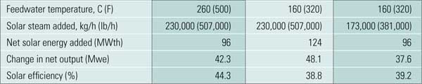
Table 3. Effect of feedwater supply temperature on combined-cycle performance for with a medium temperature CSP. Source: Bechtel Power Corp.
Alternatively, solar thermal input to an ISCC can be used to reduce the plant’s fuel consumption for a given power level. Note that reducing gas turbine fuel consumption also reduces gas turbine power and exhaust energy. For the same plant net output with 100 MWth of solar energy input, plant fuel consumption is reduced by ~8%.
Note that some Fresnel systems also fall into the medium-temperature category, although pressure limitations of that design prevent their use in developing HP saturated steam. Given these pressure limitations, the integration of Fresnel systems would be more suitable for a low-temperature system.
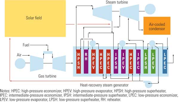
High-Temperature Solar Technology. Power tower systems can generate superheated steam at high pressures and up to ~545C (1,013F). These conditions allow the admission of solar-generated superheated steam directly into the HP steam line to the steam turbine. In addition, steam is reheated in the power tower, much as it is in the HRSG (Figure 5). This configuration requires virtually no HRSG design changes because the solar boiler superheats and reheats the solar-produced steam.
As with the medium-temperature technology, the location of the feedwater takeoff to the solar field is an important parameter to consider in the plant design.
5. High-temperature ISCC. Source: Bechtel Power
Low-Temperature Solar Technology. Most Fresnel systems fall into the low-temperature category. These systems generate saturated steam up to ~270C (518F)/0.55 MPa (80 psia). This pressure is too low to allow integration into the HP system of the steam cycle. Basically, two options exist: Either generate saturated steam at ~3 MPa (435 psia) and admit it to the cold reheat line or generate steam at ~0.5 MPa (72.5 psia) and admit it to the LP steam admission line (Figure 6).
6. Low-temperature ISCC. Source: Bechtel Power
As with the other solar systems, taking the feedwater supply from the optimum location in the steam cycle is vital to maximize the cycle efficiency. However, in low-temperature systems there is less flexibility in the selection of the feedwater takeoff point because the takeoff temperature must be below the saturation temperature of the steam being generated.
Economic Considerations
Which of these CSP technologies is the most attractive to a potential ISCC developer? Once the technology options are identified, a detailed economic analysis must be performed to determine the levelized cost of electricity for the specific site under consideration, including capital costs, O&M costs, and performance data for all the different operating scenarios. This analysis must look at different MWth solar inputs to the combined cycle and different solar technologies that generate different steam conditions.
Also, site data must be carefully examined to quantify the energy contribution of the solar facility that will define the overall performance characteristics of the ISCC. Data available from the National Renewable Energy Lab (NREL) give hourly dry bulb temperature, relative humidity, and solar insolation for many sites. Software programs, such as the NREL Solar Advisory Model (SAM), help analyze a particular plant configuration. Figure 7 illustrates the results of one such preliminary analysis. It shows average solar thermal energy production in MWth for January and August for each hour of the day.
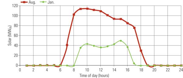
7. Cyclical solar energy. These are typical solar energy production curves for a summer day and a winter day. The shape of the curves will be specific to the site selected. Source:Bechtel Power
Figure 8 illustrates the performance characteristics of our hypothetical 2 x 1 combined-cycle plant modified to accept 100 MWth of solar energy input in the form of HP saturated steam converted into electricity at essentially the bottoming cycle efficiency. The bottom line in the figure is the "no solar" case used for comparison with a conventional combined cycle.
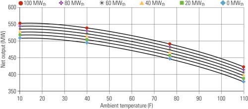
8. Mixing gas and solar. The potential additional power generated by an ISCC is illustrated here. The bottom line represents the case where the solar field produces no thermal energy, which is equivalent to a conventional combined-cycle plant. Source: Bechtel Power
An advantage of solar energy over other forms of renewable energy is that it produces energy when it is most needed: during peak times of the day and year. "Time of delivery" pricing, where energy payments vary with time of day and attempt to mirror the cost of generation, can greatly help a solar facility. For example, some Pacific Gas & Electric Co. power purchase agreements include time of delivery pricing that values energy produced during "super-peak" periods (from June through September between 1 p.m. and 8 p.m. Monday through Friday) at rates almost double those at any other time of year. The available pricing structure must obviously be included in an economic analysis to assess the viability of any hybrid solar plant configuration.
Options for Integrating Solar with Rankine Cycles
Many of the same issues confronted when integrating solar technology with a combined cycle are similar to those encountered when integrating solar technology with Rankine cycles — with one notable exception: All of the electrical power produced in a conventional steam plant is produced by burning fossil fuels. This fact can be very advantageous for a hybrid cycle in which solar energy displaces fossil fuel energy. In addition, boiler efficiency typically increases slightly as boiler load is reduced, so using solar energy to reduce boiler load to save fuel is an added advantage.
Integration with Rankine cycles will only be touched on here, as most integration applications to date have focused on ISCC.
Medium-Temperature Solar Technology. A typical subcritical Rankine cycle power plant has turbine throttle steam conditions of ~16.6 MPa (2,400 psia) and 538C (1,004F). As with a combined cycle, medium-temperature solar technology can generate saturated or slightly superheated steam injected upstream of the superheater sections of the boiler. However, integration of solar steam into the boiler proper is a much more complicated proposition than in a combined cycle due to the higher gas temperatures involved and complex boiler fuel controls.
Most solar energy options assume the steam produced by a CSP system will heat feedwater to displace turbine extraction steam to the feedwater heaters (Figure 9). Reducing or eliminating extraction steam to feedwater heaters appears to be the most practical application for medium-temperature solar integration, as it avoids complex issues of integration with the boiler and its controls.
9. Medium temperature solar integrated Rankine cycle. Source: Bechtel Power
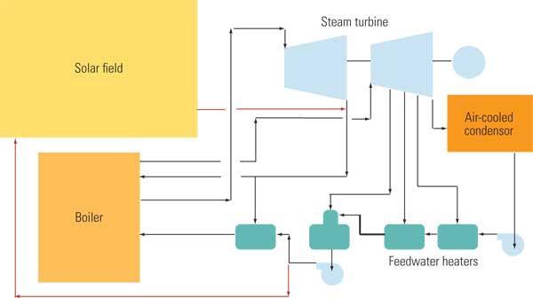
High-Temperature Solar Technology. Power tower technology can be used to generate superheated steam for injection into the main steam line to the turbine. The same amount of cold reheat steam can be extracted and reheated in the solar field (Figure 10). This approach minimizes potential integration problems with the conventional steam boiler.
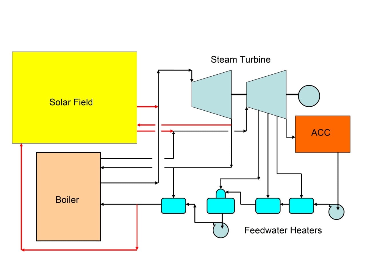
10. High-temperature solar integrated Rankine cycle. Source: Bechtel Power
Low-Temperature Solar Technology. Options for integrating low-temperature solar technology are limited primarily to generating steam or heating feedwater to reduce the turbine extraction steam to feedwater heaters.
Controls and Transient Behavior
Any solar hybrid cycle must include an in-depth analysis of the transient behavior of the entire system, including the solar steam source. Because there is no field experience with utility-scale ISCC, the true complexity of the problems associated with normal start-up, normal and emergency shutdown, and load transient behavior (to name a few scenarios) must be carefully analyzed.
The final dynamic model will be of an integrated system capable of predicting steam temperature and pressure variations during steady-state and transient conditions. The controls engineers can then develop the necessary controls and identify the instrumentation to protect the equipment and provide for operator safety. Finally, the complete system must be cost-optimized to minimize field installation and O&M costs over the plant’s lifetime.
-—Dave Ugolini (dugolini@bechtel.com) and Dr. Justin Zachery (jzachary@bechtel.com) are senior principal engineers for Bechtel Power Corp. Hyung Joon Park hjpark@bechtel.com) is a financial analyst for Bechtel Enterprises. Dr. Zachery is also a POWER contributing editor.