Shrinking water supplies will unquestionably constrain the development of future power plants. A hybrid system consisting of concentrated solar thermal power and desalination to produce water for a plant, integrated with a combined cycle or conventional steam plant, may be the simple solution.
Desalination is a water treatment process in which seawater is separated into two process streams: a freshwater stream with a low concentration of dissolved solids and a brine or reject stream with a high concentration of dissolved solids. The desalination device, regardless of type, requires energy to operate and do the separation.
The primary commercial technologies for desalination fall into two main categories: thermal desalination and membrane desalination. Thermal desalination systems utilize energy in the form of heat to effect a phase change of the seawater (from liquid to vapor phase) to separate freshwater from brine. Membrane desalination devices use a pump to force water through a semi-permeable membrane, again separating the freshwater from brine. Reverse osmosis (RO) membranes are most commonly used in this type of desalination system.
Thermal Desalination Technology
Thermal processes utilize energy in the form of steam or hot water, extracted from a power plant steam cycle or produced by an auxiliary boiler, to boil the seawater. Vapor released from the boiling seawater is condensed and collected as product water. Water recovery from thermal desalination processes can range from 10% to 50% of the influent seawater, depending on the technology selected.
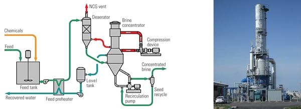
Multi-stage flash evaporation (MSF) desalination systems have traditionally been preferred because of their reasonable cost, good efficiency, and long experience. However, in the past 20 years, multiple-effect distillation (MED) technology has become the primary thermal desalination option with the development of new designs that permit lower operating temperatures, minimize corrosion and scaling, and increase efficiency. Figure 1 depicts a typical MED system.
1. Multiple-effect distillation system. Courtesy: Bechtel Power
MED systems are designed with multiple evaporator stages, called "effects," which evaporate seawater to produce desalinated water. While in theory, MED systems may be built with an arbitrarily large number of effects, normally, in large desalination plants the number varies between 8 and 16 due to the low temperature drop per effect. In this type of thermal desalination system, seawater is heated to approximately 70C (158F) by steam from an external source.
Boiling occurs in the sequence of effect vessels, each held at a lower pressure than the last. Because the boiling point of water decreases as pressure decreases, the vapor boiled off in one vessel can be used to heat the next. Only the first vessel (at the highest pressure) requires an external source of heat. The seawater and external steam source both enter the MED system in the first effect on opposite sides of the heat exchanger tubes. Steam is fed to the inside of the tubes, and seawater is sprayed over the outside of the tubes in a typical effect. The seawater, upon contacting the heat exchanger tubes, begins to boil. The vapor produced is collected and is transported to the second effect on the inside of the second effect’s heat exchanger tubes. The heating steam from the first effect condenses inside the first effect’s heat exchanger tubes and is returned to the power plant or auxiliary boiler as condensate.
Concentrated seawater brine in the first effect is collected in trays and transported across the outside of the heat exchanger tubes in the second effect, where again it boils by heating and the pressure change. This process continues throughout the series of effects. After the final effect, the vaporized water that has collected on the inside of the effect heat exchanger tubes is cooled and condensed with seawater in a final heat exchanger.
Most MED designs today also include a thermal vapor compressor (TVC) to increase system efficiency. A TVC recycles some of the vapor produced in the desalination process to reduce the total amount of steam required to drive the process. A TVC is essentially a steam ejector that entrains low-pressure vapor from a downstream effect with motive steam and discharges the mixture into the first effect.
Though MED technology was originally developed in the 1960s, it did not begin to gain widespread acceptance until the 1990s. Today, MED plants are generally built in units of about 100 m 3 /day up to 36,400 m 3 /day (0.03 to 8 mgd), allowing this design to be utilized in smaller volume applications. Multiple units may be combined in one plant to further increase capacity. The system produces a very high-quality product water from sea or brackish water with a total dissolved solids (TDS) concentration of 25 mg/l or less. The desalinated water produced is so pure that minerals are normally added back to make it suitable for human consumption and use as potable water.
Membrane Desalination Technology
Membrane desalination technology today is dominated by systems that are designed to utilize seawater RO (SWRO) membranes as the freshwater/brine separation device. In SWRO desalination systems, the water in a pressured saline solution is separated from the solutes (dissolved solids) by forcing it through a semi-permeable membrane. Energy, in the form of electricity, is employed to power pumps to reverse the process of osmosis and force water through the membranes. The salt water is pumped into the RO pressure vessel, where it is forced under pressure against the membrane. As a portion of the water passes through the membrane, the remaining feedwater increases in salt content proportionally. This concentrated portion of the feedwater (known as the brine or the reject) is discharged without passing through the membrane.
A high-pressure booster pump supplies the pressure required to force the water through the SWRO membranes. This pressure can range from 6.9 to 18.6 bar (100 to 270 psig) for brackish water to 38 to 83 bar for seawater applications. Today’s membrane designs are capable of removing salts with very high efficiency — obtaining up to 99.8% salt rejection. POWER reviewed a utility-scale SWRO system that was recently constructed in China in the April issue: "Sub-Sea Water Treatment System Provides Reliable Supply for the Huaran Power Plant."
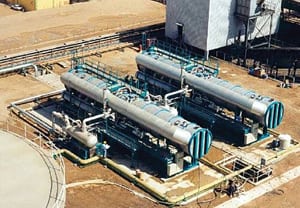
The primary cost of operating an SWRO system is the energy required to increase seawater pressure high enough to overcome the system osmotic pressure and force the seawater to permeate the RO membranes. The actual pressure drop across the RO membranes is only about 0.5 to 1 bar, depending on the number of elements per pressure vessel, so the RO reject stream is released at high pressure. Energy recovery devices (ERD) such as Pelton turbine wheels or pressure exchangers are used to recover the energy from the reject stream and reduce operating costs. An ERD can reduce the energy consumption of the SWRO booster pump by approximately 35% to 45%. A typical seawater reverse osmosis skid is shown in Figure 2.

2. Reverse osmosis system. Courtesy: Bechtel Power
Membrane desalination processes produce product water of lesser quality than that produced by thermal processes. TDS concentrations in desalinated water produced using membrane processes vary, depending on influent seawater TDS concentrations, but they are typically in a range suitable for most industrial applications and for potable water usage (<500 mg/l TDS). Additional stages of treatment (that is, second-pass membrane treatment) may be required to produce water suitable for some industrial needs (such as boiler makeup water).
Typical water recovery is in the range of 35% to 60% of the influent seawater from membrane desalination processes — better than that of thermal processes. However, water recovery is highly dependent on the quality of the influent seawater.
Membrane desalination systems have a much smaller footprint than typical thermal desalination processes, which reduces installation costs. On the other hand, more pretreatment of seawater is necessary for SWRO systems to prevent membrane fouling.
Solar Thermal Concepts
Concentrated sunlight has been used to perform useful tasks from ancient times. In 1866, a French inventor successfully powered a steam engine with sunlight, the first known example of a concentrating solar-powered mechanical device. In general, concentrating solar power (CSP) technologies require direct sunlight to function and are of limited use in locations with significant cloud cover.
CSP systems require several components to produce electricity: a concentrator, receiver, storage or transportation system, and power conversion device. The CSP technology type determines the different options for interface with a conventional fossil-fired plant. Table 1 summarizes the types of CSP technology and their thermal output; short discussions of each technology follow.
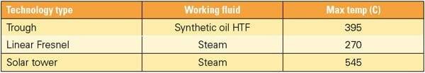
Table 1. Key features of CSP solar technologies. Source: Bechtel Power
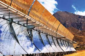
Trough Collector. The parabolic trough is considered the most proven CSP technology. Since the 1980s, more than 350 MW of capacity have been placed in operation using this technology at the Solar Electric Generating Station (SEGS) plants in California’s Mojave Desert. (The 64-MW net Nevada Solar One project, using trough technology, was profiled as a POWER Top Plant in December 2007.)
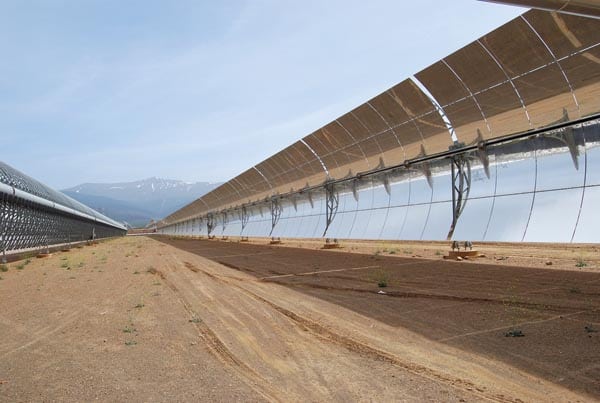
The parabolic trough is basically a very large curved mirror. Its parabolic shape is designed to concentrate the solar energy and reflect it onto a linear focal point. The mirror position follows the sun’s movement in the sky using a motorized device. The cylindrical parabolic reflector is traditionally made of thick glass-silvered mirrors (4 mm to 5 mm), but thin glass, plastic films, and polished metals are also used. A series of typical trough collectors is shown in Figure 3.
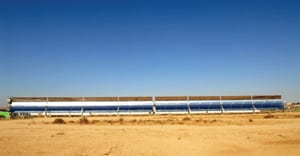
3. Solar trough technology system. Courtesy: Siemens Concentrated Solar
A receiver tube is located at the focal point of the parabolic mirror trough. The metal tube is coated with special coatings aimed at maximizing energy absorption and minimizing heat losses. Flowing inside this tube is a conventional heat transfer fluid (HTF), which absorbs energy from the concentrated sunlight. The metal tube is enveloped by a glass tube. The space between the absorber and the glass tube is kept under vacuum to reduce heat losses. A support structure made of metal holds the receiver in accurately at the focal point of the mirror trough that must be sufficiently rigid to resist the twisting effects of wind while maintaining optical accuracy. At the same time, the cost of the structure as well as the cost of on-site assembly and installation should be as low as possible.
Several receivers are typically connected to form a loop. Many loops are needed to produce the heat required to bring a large amount of HTF to the maximum allowable temperature. In locations with good solar radiation, about 4 to 5 acres are needed to produce 1 MW of capacity.
The hot HTF from all the plant’s loops are combined and sent to a steam generator. The steam generator is a heat exchanger where the HTF heat enters on the shell side and transfers heat to the incoming water in the first section to produce steam. The steam reenters a second section of the heat exchanger to produce superheated steam. From this point on, the power block converting the steam into electricity contains conventional steam plant components: steam turbine, heat sink, feedwater heaters, and condensate and boiler feed pumps.
Maximum HTF temperature is around 395C, mainly due to the operational limitations of the synthetic oil HTF. The field temperature from Nevada Solar One is 390C from a field area of 357,000 m 2. The plant’s thermal efficiency is reported by the National Renewable Energy Laboratory (NREL) as 37.6% when operating at 100 bar steam pressure. Similar performance numbers are reported by NREL on SEGS VII through IX.
Trough technology is mature and has been demonstrated on relatively large-scale plants. But there are several disadvantages inherent in the design. For example, the maximum HTF operating temperatures dictate relatively lower cycle efficiency. Also, the additional heat exchanger between the Rankine cycle working fluid and the fluid heated by the sun adds complexity to the cycle and further reduces its maximum operating temperature.
Fresnel Collector. The linear Fresnel solar collector is a line focus system similar to the parabolic trough. Unlike troughs, however, it uses an array of nearly flat reflectors to concentrate sunlight. Normally, these are one-axis tracking, flat mirrors fixed to a steel structure on the ground. Several frames are connected to form a module, and the modules form a long row up to 450 meters (1,475 feet) long. The receiver employs one or more tubes located above the mirrors at a determined height. These metal tubes have an absorbent coating, similar to trough technology. Water, or a mixture of water and steam with quality of around 0.7, flows within the tubes. At the end, the water and steam are separated and saturated steam is produced either for process heat or to generate electricity using a conventional Rankine cycle power block (Figure 4).

4. Linear Fresnel technology system. Courtesy: Ausra
Today, the largest Fresnel collector project is the Kimberlina Solar Thermal Power Plant demonstration project located in Bakersfield, California. The solar field aperture area is 26,000 m2, with collectors arranged in three lines, each 385 meters long. The plant can produce up to 5 MW with a steam turbine operating at 40 bar steam pressure. Water is used as the HTF. The plant has been operational since late 2008, according to NREL.
In principle, the Fresnel system offers several advantages, including these:
-
Direct generation of steam without the use of an intermediate HTF.
-
Less stringent requirements for optical accuracy.
-
The design allows more factory assembly.
-
Use of conventional off-the-shelf materials.
-
Structural design less subject to wind impact.
However, several disadvantages also exist, including these:
-
Technology not as mature as trough, with only recent, relatively small-scale commercial development taking place.
-
Lower power cycle efficiency due to lower steam temperature.
-
Lower optical efficiency and increased heat losses due to absence of insulation around the receiver tubes.
Expect the steam cycle efficiency to improve as technology suppliers are able to increase operating temperatures up to 450C.
Solar Tower. In this concept, a boiler on top of a tall tower receives concentrated solar radiation from a field of heliostats, which are two-axis tracking mirrors. The heat transfer media could be water or steam, molten salt, liquid sodium, or compressed air.
In the more conventional arrangement, the working fluid is water (Figure 5). The water temperature is higher than in line-focus systems — close to 545C. The power tower can be connected to molten salt storage, thus allowing the system to extend operating hours or increase capacity during periods when power is most valuable. The main advantage of this technology is its ability to provide high-temperature superheated steam. The design requires accurate aiming and control capabilities for the solar field heliostats to maximize efficiency and avoid potential damage to the receiver on top of the tower.
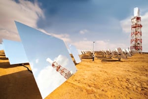
5. Solar tower technology. Courtesy: Bright Source
Integrate the Disparate Systems
Several scenarios were considered in analyzing potential integrated desalination plant/CSP power plant options. As part of the case studies, the first parameter varied was the location of the CSP-desalination/power plant facility. Three locations, each possessing plentiful insolation (exposure to sun) and lacking freshwater supplies, were considered:
-
Egypt on the coast of the Mediterranean Sea
-
Saudi Arabia on the Red Sea
-
California, U.S., on the Pacific Ocean
For each location, installation of three different-size desalination facilities, each designed to provide freshwater for a different power plant configuration that would supply water for a new plant and a nearby town, was evaluated:
-
2,500 m3 /day (0.7 mgd)
-
7,200 m3 /day (2 mgd)
-
45,500 m3 /day (12 mgd)
For all three physical locations and all three power plant/desalination system configurations, installation of both MED and SWRO as the desalination technology was considered. Tables 2 and 3 provide a summary of the desalination/power plant configuration scenarios investigated.

Table 2. Summary of MED options evaluated. Source: Bechtel Power
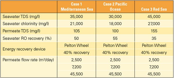
Table 3. Summary of SWRO options evaluated. Source: Bechtel Power
The primary aim of CSP plants is to generate electricity, yet a number of configurations enable CSP to be combined with various desalination methods. When compared with photovoltaic (PV) or wind, CSP could provide a much more consistent power output when combined with either energy storage or fossil fuel backup. The most suitable options will be described here.
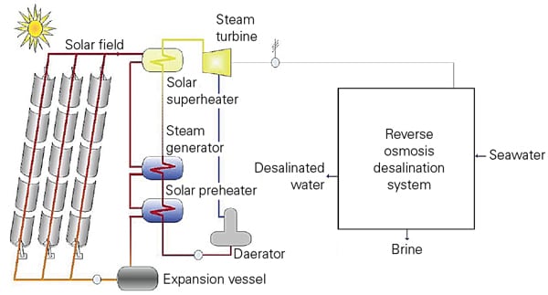
A typical solar trough configuration combined with a MED system where steam generated is first expended in a noncondensing turbine and then used in a conventional manner for desalination (Figure 6). The steam generated by a trough plant is superheated to around 380C. As described earlier, the steam temperature for the MED plant is around 135C. Therefore, there is sufficient energy in the steam to produce electricity before it is used in the MED plant. It is important to emphasize that water production is the main purpose of the plant — electricity is a byproduct. While conventional combined-cycle (CC) power plants can be configured in a similar manner for desalination, a fundamental difference exists in the design approach for solar and for fossil fuel – fired plants. The fuel for the solar plant is free; therefore, the design is not focused primarily on efficiency but on capital cost and capacity of the desalination process. In contrast, for the CC power plant, electricity production at the highest possible efficiency is the ultimate goal.

6. Solar parabolic trough power plant with oil steam generator and MED desalination. Source: Bechtel Power
As described previously, the RO system is an alternative to thermal desalination processes. In this case as well as in MED, the steam generated by the solar plant can be used through a steam turbine to produce the electric power needed to drive the RO pumps. As an alternative for large, multi-unit RO systems, the high-pressure seawater can be provided by a single pump driven by a steam turbine. This arrangement is similar to the steam-turbine-driven boiler feed pumps in a fossil fuel power plant. Obviously, a feasibility study must be conducted to determine the most appropriate solution for each situation.
Often, MED and RO are compared in terms of overall performance and specifically for energy consumption. Based on several Bechtel internal studies as well as open literature, one can conclude that in specific cases, the CSP and RO (Figure 7) require less energy than a similar CSP and MED combination.
7. Solar parabolic trough power plant with oil steam generator and SWRO desalination. Source: Bechtel Power
However, an analysis presented by Franz Trieb ("Concentrating Solar Power for Seawater Desalination," DLR report, Stuttgart, 2007) suggests that, for several locations, CSP/MED requires 4% to 11% less input energy than CSP/RO. Therefore, before any decision can be made on the type of desalination technology to be used, it is recommended that a detailed analysis be conducted for each specific location, evaluating the amount of water, salinity of the input seawater, and site conditions. It appears that CSP/MED provides slightly better performance at sites with high salinity, such as the Arabian Gulf, whereas CSP and RO appear to be more suitable for low-salinity waters in the Atlantic Ocean or Mediterranean Sea.
One additional advantage of the RO system is that the solar field might be located away from the shoreline. The only connection between the two is the production of electricity to drive the RO pumps and other necessary auxiliary loads.
Linear Fresnel technology development could have a significant impact on desalination if its design, thermal performance, and cost can meet industry expectations. Operating within the necessary temperature ranges for MED as well as RO, despite the lower optical efficiency, linear Fresnel may prove to be the best solution for standalone desalination plants. Figure 8 depicts a linear Fresnel system arrangement that includes a steam turbine with a geared system for direct drive of the seawater pumps.
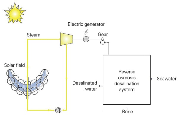
8. Linear Fresnel power plant with RO system. Source: Bechtel Power
CSP Desalination and Storage
A key issue with deploying renewable energy conversion systems is their intermittent nature. Wind, PV, and CSP generate power only when the wind blows and the sun shines. Obviously, the benefits of energy storage are invaluable in improving the grid stability, power quality, and continuity of supply. When compared with heat or electricity, the desalination product — water — can be stored very economically. This provides an additional advantage for combining solar thermal plants with desalination.
Due to variations in seasonal and diurnal solar heat input, many solar fields for CSP are designed to match an average insolation flux. In the summer and during peak daylight hours, an excess of heat is produce by the solar field. In the absence of a storage system capable of absorbing this heat, some of the solar collectors or mirrors have to be defocused. This process is called "energy dumping." By directing this excess heat to the desalination plant, one can produce water and store it for future use. This way the capacity factor of the CSP plant could be dramatically increased and the economic picture improved.
Although water consumption remains relative flat over the entire year, electric power demand increases by more than 50% during the summer due to air conditioning loads. The combination of a hybrid solar power generation and desalination plant would allow some degree of discretionary allocation of the heat input to either of the applications — power or water — depending on the sizing of the electrical generation equipment. Some of the electrical power generated at off-peak demand conditions could be used to produce water and appropriately store it.
All the desalination technologies are striving to reduce cost, increase capacity and efficiency, and reduce environmental impact. The large number of CSP projects under development for all types of technologies — tower, trough, linear Fresnel — will lead to improved equipment, better field experience, and lower capital costs.
It’s All About the Money
In evaluating capital costs as well as operating costs, one important criterion is the size of the solar field for each of the desalination technologies. Figure 9 provides a comparison of the relative costs of CSP combined with RO versus CSP combined with MED. It can be seen that the solar field as well as the conventional power plant costs are higher for the RO option, but the actual desalination plant cost is lower (see Trieb, referenced above). A comparison of the equipment cost for the desalination equipment alone is shown in Figure 10.
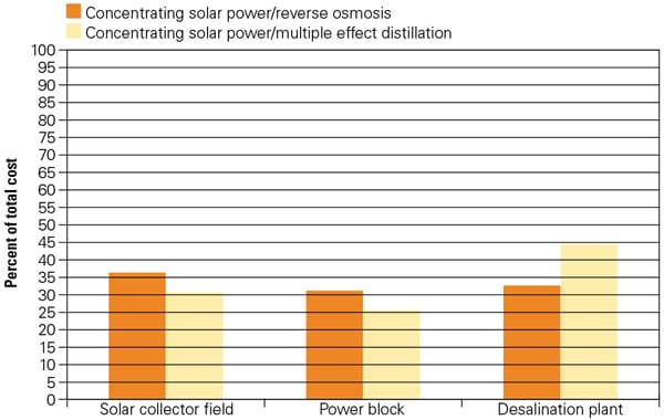
9. Cost comparison between CSP and the RO and MED desalination options for major plant systems. Source: Bechtel Power
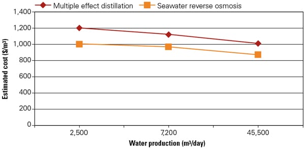
10. Cost of desalination equipment. Source: Bechtel Power
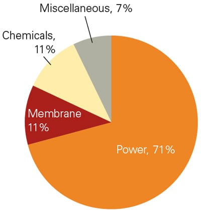
11. Typical O&M cost for an RO desalination plant. Source: Bechtel Power
It is evident that the RO systems are less expensive for all sizes of plants. When compared with conventional systems, the viability of such solar desalination systems is dependent on the escalation of fuel costs, operation and maintenance costs of combined cycles, and market price for water. The operating costs of an RO plant, presented in Figure 11, indicate that the power is the most significant contributor (72%). For a desalination plant, a key factor in cost reduction is an increase in process efficiency by improving the recovery power ratio.
—Dr. Justin Zachary is technology manager and a Bechtel Fellow for Bechtel Power Corp. Zachary is also a POWER contributing editor. Colleen M. Layman is manager of water treatment for Bechtel Power Corp.