WATER TREATMENT
Tackling substandard water sources
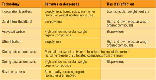
Boiler and cooling tower feedwater typically must be softened prior to use, usually with well-established processes for reducing water hardness. A growing problem for many power plant operators is maintaining adequate softening, clarification, and treated water quality while dealing with increasingly substandard source water quality. Many power plants also are being forced to adapt their process water systems so that they can use a fluctuating, off-spec water supply that is high in hardness, silica, and solids.
Luckily, innovative technologies are being developed to treat lower-quality water–and to do so within an existing or smaller footprint. For example, high-rate, small-footprint processes for water clarification, softening, and silica removal have been recently introduced to shorten retention times and provide greater flexibility in dealing with poor or varying source water quality.
Softening essentials
As the quality of source water decreases, the importance of efficient and effective water softening processes increases. Softening is essential for keeping the heating surfaces on the water side of boilers free of deposits. Various salts present in the water become less soluble as the temperature rises, and they precipitate out and adhere to the internal boiler and piping metal as soft or hard scale deposits. Dissolved minerals can precipitate out of the solution and deposit as scale on the heat exchange surfaces of evaporative cooling systems, just as in a boiler. Scaling on these surfaces decreases the rate of heat transfer, leading to increased operating costs and deterioration of equipment.
These accumulations can plug boiler tubes and piping, and can also decrease heat transfer to the point that the metal overheats, leading to costly tube failure. Contaminants can also volatilize in the steam and carry over into the turbines, creating maintenance problems and impairing turbine performance. In addition, embrittlement can occur when high caustic concentrations are trapped under scale deposits, causing cracks and leaks (see “Put a Lid on Chemical Costs,”). The pH of the water outside the scale deposits can register a safe 8.0 but be as high as 10.0 to 11.0 under the scale and directly on the metal.
The traditional water pretreatment method for softening entails the addition of lime to precipitate out the calcium, magnesium, and silica in the raw water supply. For boiler feedwater treatment, the exact process used depends on the boilers. Low-pressure boilers are less demanding, although some secondary treatment is typically applied after the lime precipitation stage. By contrast, high-pressure, supercritical boilers require high-purity, deionized water, requiring traditional softening with lime and other chemicals followed by polishing with reverse osmosis, cation and anion exchange, or electrodeionization (or all three processes in series).
Softening options
In the precipitation stage, quick or slaked lime is added to water in a rapid mix zone upstream from one or more clarifiers. Lime is added to reach the pH required for calcium and magnesium to form a solid precipitate. If the alkalinity of the source water is insufficient, an additional source of alkalinity (like soda ash) may be added to the water to further precipitate the calcium ions. The silica present in the water piggybacks with the magnesium, so in some cases an additional source of magnesium may be added to the water to help capture the silica. After the precipitation reaction, the solid precipitates formed are settled in a clarification system, where sludge is separated from the clarified water effluent. At this point, water intended for use in low-pressure boilers (below 450 psi) will typically flow through a closed sodium exchange vessel, where it contacts synthetic ion exchange resin. In this vessel, any remaining anions are exchanged for sodium.
High-pressure boilers (above 600 psi) require ultra-pure water that must be first pretreated with lime softening and then further processed through both cation and anion exchange beds. Calcium, magnesium, and sodium are exchanged for hydrogen ions in the cation beds, and sulfate, chloride, carbonate, and silica are exchanged for hydroxide ions in the anion beds.
Membrane processes are also often used to remove impurities. Reverse osmosis blocks salts, and electrodialysis with current reversal forces dissolved salts through cation- and anion-selective membranes. Following this series of demineralization treatments, some plants also further remove alkalinity from the water. The degree of “polish” achieved with these downstream processes is directly related to the effectiveness of the lime precipitation process. For example, synthetic resins deplete over time and the “cleaner” the water entering the exchange beds, the longer the interval is between regenerations. (See POWER, August 2008 for a discussion of how to select the right condensate treatment approach.)
In the past, lime softening was performed in batch systems by mixing the chemicals with raw water in a tank, allowing time for precipitation and settling, and then flowing off the clear water. Over time, this method has been improved by adding continuous-feed chemical dispensers to treat incoming water and using a separate tank for retention and settling, followed by continuous outflow of softened water from a third tank downstream.
The equipment configurations typically used today for lime softening haven’t really changed much in the past 50 years. Big, circular, solids contact or sludge blanket clarifiers are used, and the volumes that can be treated as well as the associated retention times are restrictive. Fluctuations in raw water quality and flow rate can often be difficult to accommodate. As the characteristics of the raw water change, operators must perform frequent adjustments to optimize their softening treatment.
With cold or warm lime softening methods, the flow rates of conventional systems are typically limited to less than 1.5 gpm/ft2 of settling area, with a one-hour retention time. Plus, the water is not “finished” at this point and further precipitation occurs downstream. The hot lime softening method is only slightly better, with a typical flow rate of 1.7 to 2.0 gpm/ft2, with a one-hour retention time.
Compact, high-rate softening
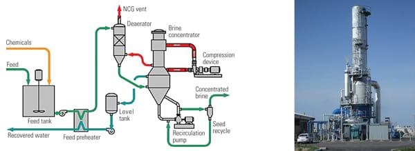
Recently introduced high-rate softening technologies can handle 12 to 32 gpm/ft2 flow rates compared to the 1.5 to 2.0 gpm/ft2 outputs from conventional lime softening methods. This increased capability substantially reduces the installation footprint required for the softening process (Figure 1), an important consideration where high-purity specifications demand intensive reverse osmosis or demineralization treatment downstream.
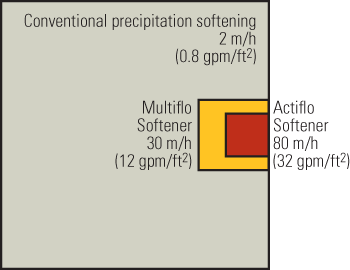
1. Compact area. Advanced water softening processes are not only more efficient, but they also require significantly less space in an already crowded power plant. Source: N.A. Water Systems
With these new treatment systems, designers have taken the principles of softening (reduction of hardness, alkalinity, silica, and other constituents in the water through lime and chemical additions) and have put them to work in a single compact treatment line. The increased overflow rates achieved by the systems translate into a higher tolerance for significant changes in raw water flow rates, compared to conventional softening processes.
Depending on the raw water’s properties, one of two high-rate technologies can be applied. The first softener system is designed to handle high flow rates with a rising velocity up to 12 gpm/ft2. This system, the Multiflo Softener, can reduce high raw water hardness concentrations of 150 to 4,000 ppm to concentrations of 35 mg/l CaCO3 and 50 mg/l magnesium in the clarified water (Figure 2). The other high-rate system, the Actiflo Softener, handles very high flow rates and has a maximum rising velocity of 32 gpm/ft2. It reduces 150 to 500 ppm hardness concentrations to 35 mg/l CaCO3 and 50 mg/l magnesium in the clarified water, and is specially adapted for silica removal (Figure 3). Both systems incorporate a new advanced precipitation reactor that promotes rapid growth of large crystals and helps increase settling velocity.

2. The Multiflo Softener water treatment process. Source: N.A. Water Systems

3. The Actiflo Softener water treatment process. Source: N.A. Water Systems
Both softening systems have a single treatment line that includes:
- A dynamic mixing zone stage that creates rapid mixing conditions to destabilize anions by adding metallic salts, if necessary.
- An enhanced precipitation reactor designed to improve the reaction of lime and carbonate ion with the hardness and natural alkalinity of water to form insoluble compounds.
- An accelerated flocculation stage to provide rapid development of large settleable flocs.
- A settling unit providing both gravity and enhanced lamella clarification. Sludge is recirculated and reinjected into the precipitation reactor to improve the precipitation kinetics and optimize chemical consumption.
The precipitation reactor is a critical component in the high-rate processes, and it allows for complete homogenization of water and chemicals. The proprietary design of the draft-tube reactor (named Turbomix) combines the advantages of plug flow and complete mixing. It reduces the reactor tank volume by suppressing dead zones and decreases reagent loss by suppressing short circuiting (Figure 4). Sludge is recirculated in the reactor so that large crystals form quickly and retention time is reduced. Recycling the sludge also increases the sludge waste concentration and thus reduces the volume of sludge for disposal.
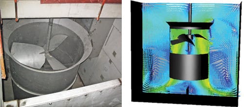
4. High-rate reactor. A proprietary draft tube reactor (L) was designed using specialized computer design tools (R) to maximize plug flow and complete mixing. Courtesy: N.A. Water Systems
The reactor immediately downstream from the precipitation reactor is used to slowly mix the precipitated particles with a flocculating polymer and promote the formation of large flocs. The Actiflo process includes the introduction of micro-sand at this point to act as a nucleus for the flocs. The ballasted flocs settle very rapidly and provide the system with its very high rising velocity. The sand is cleaned and recovered for reuse through the use of hydrocyclones. The final stage includes a clarification tank with lamella-enhanced settling.
By comparison, the Multiflo system does not use sand in the recirculation loop, but it can handle a higher solids loading than Actiflo and will provide sludge thickening in the lamella settling step. The choice between the two technologies depends upon the influent water flow rate and characteristics.
99% total hardness removal
A Multiflo Softening system was installed as part of a pilot demonstration to investigate technologies with the potential to ease demand on the Pecos watershed in New Mexico. The goal was to soften water sufficiently to prevent scaling on reverse osmosis membranes in a downstream treatment step. The raw water contained a total hardness (CaCO3) of 226 mg/l.
Four reactors and one clarifier (all components of the Multiflo system) with associated chemical dosing systems were provided. Lime and soda ash were added in the first and second reactors to remove the calcium hardness. Caustic was added in the third reactor to remove the magnesium hardness and co-precipitate silica. An anionic polymer was added in the fourth reactor to enhance solids/liquid separation.
The solids generated through chemical precipitation were then removed in a clarifier. A portion of the clarifier sludge was recirculated to the first reactor to optimize lime usage and serve as a nucleus for precipitate formation. Total hardness was reduced to 22.5 mg/l with this process, representing a 99% reduction.
–Contributed by Marta Beltran-Perez (marta.beltran-perez@veoliawater.com) an application engineer for Multiflo/Actiflo, and Larry Gurnari (larry.gurnari@veoliawater.com) power industry market manager for N.A. Water Systems, a Veolia Water Solutions & Technologies company.
MECHANICAL
Control abrasive wear in scrubber piping
Minnkota Power Cooperative (Grand Forks, N.D.) provides electric energy to 11 associated distribution cooperatives in eastern North Dakota and northwestern Minnesota. Minnkota operates two coal-fired units at the Milton R. Young Station near Center, N.D., with a combined rating of 705 MW; Unit 1 began operation in 1970 and is rated at 250 MW, and Unit 2 entered service in 1977 and produces 455 MW.
Young Station ranks as one of the lowest-cost coal-fired power plants in the U.S. The station receives lignite coal from a nearby mine, which is operated and owned by BNI Coal. The lignite coal passes through three crushers before it is sent through the coal transport lines using high-velocity, 750F air, which removes most of the moisture. The coal is then sent to the cyclone-fired boilers, where it is mixed with heated air for combustion. The plant consumes about 4.3 million tons of coal annually.
Flyash causes wear and corrosion in piping
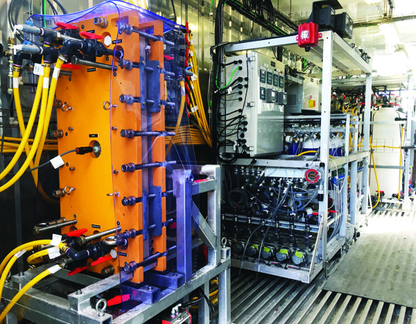
Unit 2 began to have problems with abrasion in the pipes when transporting flyash to the plant’s scrubber (Figure 5). “We have a very abrasive situation,” said Dennis Ziniel, mechanical maintenance supervisor for Minnkota Power. “The flyash is very abrasive and very corrosive.”
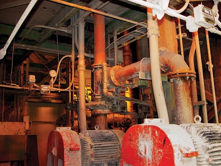
5. Flyash problems. Minnkota Power Cooperative’s 455-MW Young Station Unit 2 experienced excessive pipe abrasion and corrosion caused by transporting flyash to the plant’s scrubber. Courtesy: Abresist Corp.
The flyash is a product of burning the lignite coal. Lignite coal produces two types of ash–bottom ash and flyash–when it is burned. Bottom ash is a heavy ash that is removed as a molten slag that flows out the bottom of the boiler. Flyash goes through the boiler and is sent to the scrubber to help scrub sulfur dioxide from boiler exhaust gases.
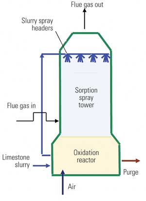
The Young Station has two scrubber towers that are about 40 feet in diameter and 160 feet tall. Inside the towers are nozzle heads that spray the flue gas as it passes through with a liquid mixture that contains a combination of limestone and flyash. The spray scrubs the sulfur dioxide out of the gas by combining it with the calcium in the limestone and flyash. This slurry is then pumped to settling ponds. The water is drawn off the top of the settling pond and recirculated and reused in the scrubber system.
Young’s staff tried fiberglass and stainless steel pipes to reduce the wear from the flyash, but other problems soon arose with those pipes. “Lined fiberglass stands up fairly well for a limited time in some applications,” Ziniel explained. “We’ve got some fiberglass here that’s been in service about 10 years, but we’re starting to see some real issues with it.”
“We also have other applications where we’ve gone with grade 316 stainless steel because it is so abrasive and so corrosive,” Ziniel continued. “But stainless steel is very, very expensive.”
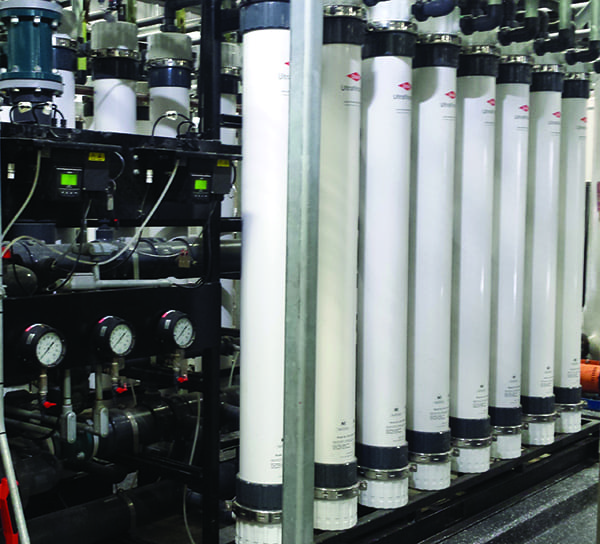
Young Unit 2 needed a solution to the pipes’ wear problems, so Minnkota Power took a look at Abresist Corp.’s cost-efficient lined piped solution. In 1988, Young Station purchased approximately 400 feet of 2-, 3- and 4-inch Abresist lined piping at half the cost of stainless steel piping priced at $200 to $300 per foot, including about 35 elbows and tees, for transporting the flyash to its scrubber. Abresist lined pipe consists of flanged steel shells lined with thick cylinders of cast basalt, an extremely hard volcanic rock that is very good at resisting sliding abrasion. Since installing the Abresist lined pipes, the pipes have not needed to be repaired or relined (Figure 6).

6. Almost legal. Abresist piping was installed at Young Station Unit 2 on the flyash transport piping 20 years ago, after plant managers rejected fiberglass and stainless steel pipe alternatives. The pipes have not required any repairs or relining since installation. Courtesy: Abresist Corp.
Lined pipes vs. fiberglass and stainless steel
“As a maintenance supervisor, I have a lot of problem areas I have to worry about,” Ziniel said. “But one of the areas I don’t have to worry about is the Abresist lined pipe, because I know it’s there and it’s working and I know I’m not going to have an issue with it.”
Though fiberglass pipes are less expensive than Abresist basalt-lined pipes, fiberglass pipes require more maintenance and repair. If the joints on fiberglass pipes are not lined up perfectly, turbulence is created and the fiberglass pipe begins to erode more quickly. “We have several spots like that where we are continually repairing it because they were not perfectly matched up when they were put together,” Ziniel noted.
Stainless steel may hold up against the flyash, but it presents other problems for the plant in addition to its higher cost. Young Station sometimes has build-up in its stainless steel pipes. When the temperature outside drops, a chemical reaction with the slurry occurs, and the slurry adheres to the inside of the pipe. A cleaning contractor then must use high-pressure washers to get rid of the build-up. “That is a very lengthy process. And very costly, too,” Ziniel admitted. “How badly the pipes are built up determines how long the contractors are here. We’ve had cleaning contractors out here for up to two weeks at $600 an hour. But, with the Abresist basalt-lined pipes we haven’t had any build-up, so Abresist lined pipes kind of give you the best of both worlds.” And since build-up is no longer a problem, the plant can save thousands of dollars that were previously spent on cleaning contractors.
–Contributed by Abresist Corp. (www.abresist.com).
I&C
Sensors and final control elements
Most information technology (IT) specialists agree that advances in basic sensor and final-control-element technology thermocouples, pressure gauges, pH meters, flow meters, valves, dampers, and pumps lag far behind the electronics and computer devices they are connected to. What they don’t necessarily agree on are the most important parameters for improvement: accuracy, repeatability, ease of service, or other metrics. This situation brings up the following analogy: Even the most well-trained and organized team will falter if the scout or code-breaker provides erroneous information.
Any plant that has upgraded its control system probably has a story like this one: At one station, the sophisticated multivariable control strategy could only operate about 40% of the time because aging sensors routinely failed, final control elements lacked linear and repeatable movements, dampers wouldn’t respond to remote control, and mechanical linkages would not provide repeatable response to the controls. The fact is that most field devices do not provide the accuracy required of today’s control systems. The situation is most acute when a distributed control system (DCS) or automation package is retrofitted to an existing plant.
Another problem: Instrumentation advances in piecemeal fashion. Predicting how many state-of-the-art instruments assembled from multiple sources would function together is virtually impossible.
Smash technology barriers
Not only are the basic devices in need of improvement, but fundamental pieces of information are missing, and direct measurement of other data would do wonders for process control. For example, even a brand new plant built today probably would not include a continuous on-line analyzer for coal; nor would it have a means to measure coal flow to individual burners. Both of these are critical pieces of information in today’s competitive, environmentally sensitive world. Some plants in Japan and Finland are correlating burner flame images to NOx levels and other combustion-quality parameters.
In corrosive environments, maintenance management would benefit enormously from strategically located continuous on-line corrosion monitors. Reliability and performance would also improve. Direct monitoring of corrosion in, say, the air heater would help operators optimize outlet flue-gas temperatures at low loads. Today’s gas turbine owners would undoubtedly appreciate an accurate, affordable means of monitoring hot-gas-path coating and/or base-metal degradation; owners of large steam turbines would appreciate a means of monitoring blade vibrations, solid particle erosion of high-pressure-stage turbine blades, or corrosion of last-stage low-pressure-module blades.
Based on a few examples, it is clear that the payoff from advanced sensors could be enormous. Acoustic leak-detection devices, now essentially standard equipment on boilers, allow plant owners to predict not only when boiler tubes will fail, but they also help pinpoint where the failed tube is. Planning time for repair is easier when repair is coordinated with planned outages or downtime, and the outage is shortened considerably when the faulty tube is located quickly. The economic advantage of reduced outage time is substantial in a competitive environment–and it may become critical. Imagine that instead of buying power to make up the difference from a plant in outage, your customers contract with someone else to supply power.
Here are two more examples:
- Slag monitors, also popular equipment at today’s plants, allow operators to program sootblowing schedules more intelligently than in the past.
- Compressor fouling in gas turbines is measured indirectly through gas turbine performance degradation, which allows on-line washes to be conducted at optimized intervals.
Each of these instruments would be easily paid for in short order through increased plant efficiency.
Striking a balance between what is done with continuous on-line measurement integrated into the IT system and what is done off-line is important. Computing power and the use of statistical and numerical analysis can often provide insight into mechanical and process trends with little hard data. The burgeoning field of hand-held and portable sensors also provides an option. Taking and analyzing a given parameter weekly or monthly, and crunching the data off-line, may be a better solution than wasting valuable data-acquisition and on-line processing time.
No silicon valves
The final control element–usually a valve, a damper, or pump/motor–is also expected to carry its control functions with it. But unlike sensors, no matter what transpires in microelectronics and systems analysis, the actuator must remain a strong, powerful, and rapidly responding piece of mechanical equipment, whether driven by air, oil, or electronics.
Nevertheless, the introduction of microprocessors and microelectronics directly at the valve or damper actuator and the digitization of signals have significantly changed actuator control, both for modulating and on/off units. In essence, the computer is onboard. This allows two-way communication and valve dynamics analysis. Calibration and verification can be done remotely, and wire-pair numbers, limit switches, and position transmitters are reduced.
A smart final control element has a microprocessor perform a servo-control algorithm for the valve or positioner that seeks to optimize the final control function; characterize the smart final control device at the valve; provide diagnostics for the electronic/pressure converter, electronics module, and communications system; communicate with the DCS; and store valve-specific maintenance information.
Integrating a digital valve with the DCS expands the operator’s view from the input/output cards in the DCS to the digital valve controller. The operator sees valuable information rather than just a process variable or implied valve position. Now the valve position can be measured and transmitted, along with the pressure driving the actuator and diagnostic information on health of the controller, actuator, and valve.
Digital opportunities
Such diagnostics on a valve will, for example, let a plant concentrate on critical maintenance, repair, or overhaul during a scheduled outage. Calculated information covers bench set, spring rate, and seat load. Graphical information on the valve signature, hysteresis, input vs. output signal, and step response helps eliminate need to connect extra equipment for local diagnostics or take the valve to the shop for detailed diagnostics. In short, smart control elements lead to automation of the maintenance functions and blend intelligently with your maintenance management system.
Assessing the integration of information with equipment would not be complete without addressing variable-speed drive (VSD) technology. Although pumps and motors are not considered final control elements the way dampers and valves are, they are modulated to optimize process control and thus take signals from the information system. Motors, for example, drive induced- and forced-draft fans, large valves, and boiler feed pumps. Motors are thought of as constant-speed machines. Yet in fan and pump drives, higher overall efficiency and greater operating flexibility result from variable-speed operation of the motor than from throttling flow.
Modern electronics has made possible widespread use of variable-frequency power supplies. Because machine speed depends directly on applied frequency, voltage must be lowered along with the frequency to vary speed. Logic circuits and variable silicon-controlled rectifier firing angles in the power supplies readily accomplish this. Three types of variable-frequency electronic drives are the voltage-source inverter, current-source inverter, and pulse-width-modulated device. In all three, a solid-state rectifier section converts AC power to DC. An inverter then transforms the DC to an AC adjustable voltage and frequency.
Many functions that were once centralized for VSD can now be executed locally. Powerful microprocessors and fieldbuses help in this regard. Drives of the future will likely include standard modular hardware platforms and allow the unit to be customized through software to match site requirements.
–From the editors of POWER