SYSTEM RELIABILITY
The NERC auditors are coming
The persons responsible for reliability (responsible entities) at utilities and other participants in the U.S./Canadian bulk power industry are preparing to have their companies’ compliance with the North American Electric Reliability Corp.’s (NERC’s) mandatory reliability standards audited by teams from NERC Regional Entities (REs). The audit schedule for 2008-2010 should have been posted on NERC’s web site (www.nerc.com) by the end of October.
Transmission operators, balancing authorities, generator owner/operators, and the other functional responsible-entity categories are gathering documentation and other evidence to demonstrate their compliance with the reliability standards to the audit teams. NERC REs will notify entities of the date of their audit and which standards it will address. NERC posted Reliability Standards Audit Worksheets for 40 different reliability-related activities on its web site this May, ahead of the June 1 effective date of the standards. The site visit will conclude with an exit presentation by the audit team and the passing out of an audit evaluation form to be filled out by audit team members and the audited entity.
New compliance challenges
As responsible entities vet the standards applicable to their category, they are finding that, in most cases, compliance is being achieved. Their next challenges are to ensure that all internal departments know which activities they must perform and document and that proof of compliance is readily accessible in a convenient format. For many participants, the challenge of compliance has become a question of “how” and “where,” rather than “if.”
Responsible entities are preparing for the audits in various ways, from insisting on electronic documentation, to planning to record or transcribe the audit itself, to arranging for their lawyers to be present. Some are making plans to have consultants on hand for pre-audit preparation, for the audit itself, and for post-audit activities such as evaluation, settlement of alleged violations, and contributing to records needed to support litigation, if needed.
Complicating these efforts is the fact that the structure, intent, and target of some standards remain unclear and questionable. Many of the mandatory standards were adapted from voluntary standards written when most utilities were vertically integrated and housed separate functions such as balancing authority, transmission owner, transmission operator, load-serving entity, and generator owner/operator under one roof. Because deregulation unbundled many of these functions, some reliability standards and their requirements now are difficult to apply to discrete responsible entities.
In some cases, the complications resulting from unbundling even extend to registration of functional entities. For example, in some instances competitive retail power providers are being cast in the role of load-serving entities, required to account for demand-side management programs and load forecasting. NERC says it is in the process of realigning the functional model that serves as the basis of registrations. But that is little comfort to the responsible entities at new participant categories that were not part of the old industry structure. They are being told that they must comply with the new standards even as their scope of applicability is being revised.
Dazed and confused
Until discrepancies like these are resolved, confusion and anxiety in the industry will continue to grow and threaten to undermine the intent and acceptance of mandatory reliability standards. Here’s hoping that NERC auditors do not stubbornly insist on evidence of compliance from those responsible entities who are unsure even of which data to access to meet their requirements.
On the other hand, there’s no doubt that NERC and its overseer—the Federal Energy Regulatory Commission—have succeeded in raising the industry’s awareness of the standards, not to mention the penalties for failing to comply with them. Through its Work Plan, NERC will eventually resolve the questions of applicability and ambiguity. Until it does, audited entities should feel free to press their audit team on issues they feel are unclear or unsustainable under the current language of the standards.
Assuming they have prepared adequately, and made themselves aware of both the spirit and letter of the new reliability laws, responsible entities should be able to approach their audit with confidence, anticipating an active exchange with the audit team. Ideally, audits—an essential part of compliance enforcement—will enhance, rather than detract from the overall reliability of the North American bulk power system during this early phase of transition from voluntary to mandatory standards. With common-sense application of standards and the industry’s continued participation in refining them, that is an achievable goal.
—Jim Stanton (jstanton@icfi.com), POWER contributing editor and director of NERC compliance for ICF International.
INSTRUMENTATION
Winning encore for on-line pH monitoring
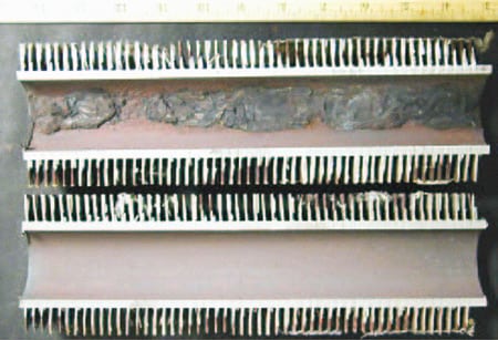
On-line pH monitoring is a quick and accurate way to determine if a high-purity boiler feedwater system has become contaminated. If impurities in the system volatize into steam in the boiler, they can end up as scale on tubes. If the impurities make it to the turbine, they can end up as scale on blades. Besides causing O&M problems, scale promotes corrosion—the culprit in about half of boiler outages and the majority of tube failures.
Although process pH instruments are today commonly used to monitor steam water circuits to safeguard against contamination, technicians at Huntley Power Station in Tonawanda, N.Y., had long relied solely on daily “grab” sample measurements because the facility was not equipped with accurate on-line instrumentation.
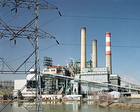
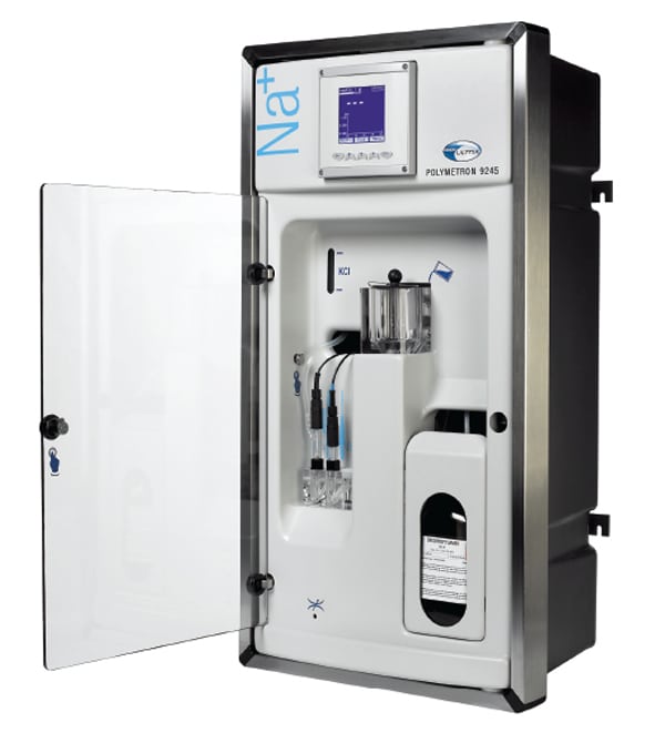
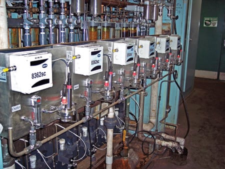
The 1999 acquisition of the Huntley plant by NRG Energy (www.nrgenergy.com) brought numerous positive changes to the station. One was the addition in November 2006 of on-line pH and conductivity sensors and other advanced water-chemistry analysis instrumentation for monitoring key points in the station’s boiler water circuits. The new sensors and instruments (Figure 1) have significantly improved the accuracy of the plant’s on-line water-chemistry monitoring program, which helps drive critical process control decisions. For example, data logging and trending of key process parameters have given the Huntley plant’s water chemistry techs new insight into the operation of the water treatment system.
1. Intruder alert. The new owner of Huntley Power Station, near Buffalo, N.Y., installed Hach pH/oxidation reduction potential panels specifically designed for accurate, reliable operation of its high-purity feedwater system. The panels address CO2 intrusion and static buildup problems that conventional pH meters have a hard time handling. Courtesy: Hach Co.
Easy act to follow
Huntley, a coal-fired baseload plant just north of Buffalo, is a key player in the western New York energy market and one of the lowest-cost producers in the state. The plant’s two 200-MW units operate at 2,550 psi and superheat temperatures in excess of 1,000F. Surface water from the Niagara River is the plant’s source of raw water. It is treated first by precipitation, then filtering, and finally by ion-exchange demineralization. The treatment plant produces about 300,000 gallons of high-purity feedwater daily.
Technicians monitor pH, conductivity, chlorides, silica, iron, and copper at various points in the plant’s water/steam cycle. The boiler water’s pH is maintained between 9.0 and 9.4, while its conductivity is kept below 5 microsiemens per centimeter (uS/cm).
On-line water chemistry analyzers had been installed at Huntley in the mid-1990s, but their performance was never reliable, according to Ray LaMarca, the plant’s chief technician. “We didn’t believe the analyzers’ readings,” LaMarca says. “We looked at them every day, but they never agreed with the results from our chem lab. As a result, we never trusted the analyzers enough to rely on them.”
Looking for a good pH meter
Unable to trust the instrumentation, operators were forced to rely exclusively on grab sample analysis—a poor situation for a baseload plant. With better on-line instruments available and NRG willing to invest in them, the decision was made to install reliable, accurate on-line feedwater analysis gear.
Selecting an on-line pH analyzer is challenging. It’s difficult to accurately read the pH of high-quality makeup water because its inherently low solution conductivity creates several problems that can lead to gross measurement errors. For example, intrusion of CO2 from the atmosphere can acidify samples of pure water, lowering their apparent pH below 7. Another common problem is static buildup, which occurs because pure water is a poor conductor of electricity. Buildups create static charges when they flow past nonconducting materials in a pH sensor and generate stray currents in the solution that may cause large errors.
Huntley Power Station ultimately selected Model 8362sc pH/oxidation reduction potential (ORP) panels from Hach Co. (www.hach.com) because they are specifically designed for high-purity water treatment systems. For example, the panels’ design addresses the problems of CO2 intrusion and static buildup that conventional pH metering system designs have trouble dealing with. The panels’ housing is completely sealed to prevent carbon dioxide intrusion, and it and the sampling chamber are made of conductive materials that minimize static charges and the potential for stray currents (Figure 2).
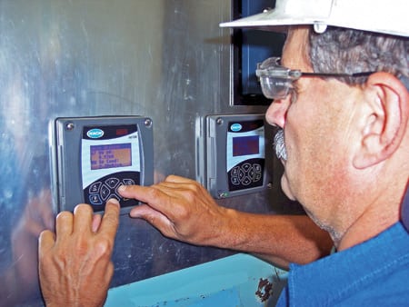
2. A well-instrumented system. Conductivity and pH units plug into controllers that each can receive data from two sensors simultaneously. Huntley Power Plant now has eight controllers serving six pH panels and 10 conductivity probes. Courtesy: Hach Co.
New home for the system
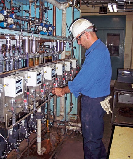
The new Hach system was installed in a new sample room (Figure 3), where it monitors the boiler water, feedwater, and hotwells of both generating units. Conductivity also is monitored on-line at several points of each water/steam circuit using separate controllers. In addition, two other sensors monitor cation conductivity in both hotwells and feedwater lines. The new pH and conductivity probes also monitor temperature, which can play a significant role in chemical changes and their interpretation.
3. New sample room. The units have built-in data loggers that collect measurements at user-defined intervals and send analog signals to the plant’s distributed control system. Courtesy: Hach Co.
The pH and conductivity units plug into the controllers, each of which can receive data from up to two sensors simultaneously. The two sensors need not be for the same parameter (a controller unit can accept conductivity, pH/ORP, dissolved oxygen, and turbidity probes). Huntley Power Plant installed eight controllers to serve six pH panels and 10 conductivity probes. The units have built-in data loggers that can collect measurements at user-defined intervals from 1 to 30 minutes, along with calibration and verification points, alarm histories, and instrument setup changes covering six months. At Huntley, the controllers are configured to send 4- to-20-milliamp signals to the plant’s distributed control system (DCS).
Tough audience
After having negative experiences with the previous on-line monitoring instruments, Huntley station technicians understandably were skeptical about the accuracy of the new system’s measurements. But their assessments to date have been quite satisfactory, according to LaMarca.
“When we compare the pH readings of the new panels to those obtained in our lab, the two sets of readings are always very close,” reports LaMarca. “They’re not identical, but they’re typically within 0.10. We’ve also found that the new units have very little drift. PH measurement is very difficult in our kind of application, and the new instruments have been good to us so far.”
LaMarca is also pleased that the new system has required little maintenance to date. Much of the maintenance entails periodically cleaning the flow cells and doing monthly calibrations, which can be accomplished easily and automatically using panel touchscreens. No repairs or replacements have been required.
The addition of data logging and real-time data monitoring capabilities has allowed technicians to respond to problems much more proactively. “The data are updated every 6 minutes on my DCS screen,” LaMarca says, “and that’s great for trending and watching the effect of changes in treatment timing.
“For example, we control pH by feeding an amine into the hotwell. The continuous monitoring and data feed from our pH meters allow us to quickly detect the changes produced by its addition. Case in point: after a shutdown of one of our units, we immediately saw a significant drop in the pH in the hotwell of the other unit, which was still on-line. As it turned out, someone had inadvertently left a tie valve on the off-line left open, allowing its feed of amine to enter the operating unit. The valve was finally closed during shutdown procedures, prompting the pH drop. Thanks to the new meters, I was quickly made aware of the situation. After I corrected it by making a series of adjustments to the amine feed rate, I was able to watch the pH of the on-line unit rise on my DCS screen.”
—By Phil Kiser (pkiser@hach.com), Hach’s industrial applications manager.
PLANT MAINTENANCE
Using balloons as temporary barriers
Making repairs to cooling water intake pipes suffering from flow-accelerated corrosion, erosion, or even zebra mussel infestation is critical to plant reliability. Maintaining the integrity of 12- or 13-foot-diameter pipes during the fixes always requires specialized experience, and occasionally some unorthodox repair methods as well.
FirstEnergy recently hired Ershigs Inc. (www.ershigs.com) to reline the intake pipes of its Perry Nuclear Power Plant near Cleveland in-situ with a fiberglass material to protect them. The first phase of the project targeted 400 feet of pipe. The bonding improves if the inside of the pipe is clean and the work is performed at an ambient temperature above 60F. So before the relining work began, temporary barriers of wood and plastic sheeting were constructed on-site and placed inside the pipes to provide for dust and temperature control—the usual tactic.
Building a 12-foot-round wood barrier can be very time-consuming. What’s more, variations in the geometry and conditions of a pipe’s inner wall make it almost impossible to create a good seal between the barrier and the wall. After this “wagon wheel” wood frame has been constructed, plastic sheeting is then attached to it. Sometimes, holes are cut in the sheeting to allow for the passage of ventilation tubes for evacuating styrene fumes and supplying fresh air to the work area.
After the piping has been relined, the wood frame and plastic barriers typically are removed and thrown in the trash. That’s what Ershigs did on the first phase of the FirstEnergy project. Unhappy with the ineffectiveness and waste of this homemade barrier method, the utility asked the contractor to devise a better scheme for isolating pipes during their repair.
The second phase of the project called for relining 200 linear feet of pipe. This time, Ershigs used inflatable bulkheads—also known as duct balloons—manufactured by Scherba Industries Inc. and distributed exclusively by G.R. Werth & Associates, Inc.

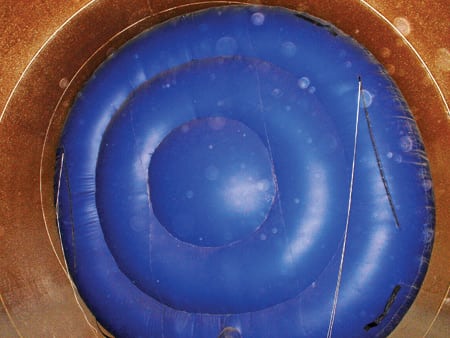
4. Put this in your pipe. Ershigs Inc.—a designer, manufacturer, and installer of corrosion-resistant, fiberglass reinforced plastic fluid-handling structures and piping systems—used duct balloons to prevent styrene fumes from escaping the work area during a recent intake-pipe relining project at FirstEnergy’s Perry nuclear plant. Courtesy: G.R. Werth & Associates Inc.
The duct balloons (Figure 4) are made of a heavy-duty, tear- resistant material that conforms to any imperfections in the inner diameter of a pipe. Each balloon is equipped with a 120-V high-pressure blower system that remains on at all times to keep the balloon fully inflated, even in the event of a small hole or cut. Should more extensive damage occur, it can be repaired quickly using the supplied patch kit.
To meet the needs of the second phase of the Perry project, Scherba and Werth supplied two duct balloons—one 12 and the other 13 feet in diameter. Each included a 6-foot by 3-foot access door with Velcro closure flaps to allow workers to pass through the balloon while it remained fully inflated. Each balloon also was equipped with a 20-inch-diameter access hole with Velcroed flaps (Figure 5) to facilitate passing a vent line through it.
5. Easy in, easy out. A side view of a Scherba Industries duct balloon, showing the access door in the front. G.R. Werth & Associates Inc.
A duct balloon weighs less than 50 pounds and inflates in under 2 minutes. A large deflation zipper enables it to be removed from service in less than 1 minute. Grab handles make it easy to put a balloon in place, and anchor rings provide tie-down points to prevent it from being moved by positive pressure inside the pipe.
—For more information, visit www.ductballoon.com or contact Gary Werth (gary@grwerth.com ) of G.R. Werth at 630-564-7471.
ENERGY EFFICIENCY
How data logging can cut power bills
One of the greatest challenges facing building owners and facilities professionals today is finding ways to reduce energy costs. The challenge can be even greater in factories full of electricity-hungry production equipment.
Air compressors, for example, are often a factory’s largest energy consumers. According to the U.S. Department of Energy, the majority of compressed-air systems at small and midsize industrial facilities have energy-efficiency opportunities.
Concerned about its factory’s high and rising electric bill, a New York-based metal products manufacturer recently hired Power Concepts LLC (www.powerconceptsllc.com), a Manhattan-based consulting engineer, to conduct an energy audit at its plant. Specifically, the company wanted to monitor the run times of a number of air compressors in the factory to better understand their consumption patterns and pinpoint where energy-saving opportunities existed.
First, do an audit
Betsy Jenkins, director of Power Concepts’ energy field team, led the audit. She explains, “our client believed that air compressors were consuming most of the factory’s energy. They wanted us to confirm that by calculating precisely how long several operated over a typical period. With that information in hand, we would then be able to recommend steps the client could take to cut the factory’s power consumption.”
To monitor the compressors’ run times, Jenkins chose HOBO State (on/off) data loggers from Onset Computer Corp. (www.onsetcomp.com). She did so as a result of her experience, as well as the units’ excellent reputation. “In our line of work, we have to make sure that our recommendations are based on accurate data,” Jenkins says. “That’s where HOBOs really shine, and it doesn’t hurt that they’re very reliable and inexpensive, too.”
HOBO State loggers (Figure 6) are compact, battery-powered devices used to track changes in the operating status of a piece of equipment. In practice, a unit does just one job: recording every time that, say, a motor or compressor turns on or off, as well as the direction of the transition. For this customer, Jenkins’ team attached one HOBO to each of the factory’s three main compressors and then let it monitor changes in status over a two-week period (Figure 7).
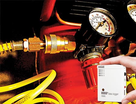
6. On the job. A Hobo State unit monitoring transitions of an air-operated valve. Courtesy: Power Concepts LLC
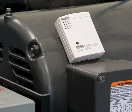
7. Big iron, small plastic. Another kind of Hobo, riding the rails of a compressor motor. Courtesy: Power Concepts LLC
After two weeks’ worth of data had been recorded, the information was uploaded to a PC and analyzed using Onset’s HOBOware Pro graphing and analysis software. The analysis indicated that compressor run times were unusually high, verifying the customer’s gut feeling.
Then, apply the results
Jenkins and her team then performed a second, more in-depth evaluation of the factory while it was shut down, during lunch hour. They detected several places where compressed air was leaking out of fittings. In one case, they noted a compressed air nozzle whose actuating handle had been taped open to disperse fumes.
“Because we conducted our site survey when the building was quiet, we were able to hear hissing sounds that no one had noticed before,” Jenkins explains. “We also discovered that one operator was using a compressor nozzle as a fan to blow fumes away from his welding machine. He had no idea that doing so was costing the company a ton of money. He could have had the fumes dispersed much more cheaply by asking his boss to have a small fan mounted near the machine.”
According to Jenkins, the data loggers also were instrumental in helping her client understand that a large portion of the factory’s power consumption was attributable to several leaks in air compressors. “Before conducting the audit, our client didn’t realize how often the compressors were running. Now he does, and we expect that our recommended energy conservation measures—plugging those leaks, for example—will save him a tidy sum,” concludes Jenkins.
—Contributed by Onset Computer Corp. (www.onsetcomp.com).