GRID RELIABILITY
New CIP standards leave questions unanswered
This January, the Federal Energy Regulatory Commission (FERC) issued Order No. 706 approving a set of eight reliability standards for critical infrastructure protection (CIP) developed by the North American Electric Reliability Corp. (NERC). The CIP standards require responsible entities (REs) at certain users, owners, and operators of the U.S. bulk power system to comply with specific requirements to safeguard critical cyber assets. In many ways, they are the centerpiece of the larger set of NERC reliability standards that apply to modeling, protection systems, and facility ratings, among other areas.
Though NERC’s CIP standards are not as stringent as those of the National Institute of Standards and Technology (NIST)—indeed, some consider the latter superior—complying with them could be more costly than complying with other grid reliability standards now in effect. Although, in many cases, the other standards require a more granular and specific documentation procedure for activities, they are more operationally directed and already part of an RE’s routine business. The CIP standards, however, are new to almost everyone and require a retooling of business practices that could raise costs considerably.
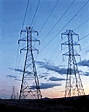
Pay a little now, or a lot later. REs would be wise to pause and think a moment before decrying the potential additional compliance costs. One can argue that those costs to power generators, transmitters, and distributors pale in comparison with those caused by the 2003 Northeast blackout, a scenario that many fear could be repeated if a substantial breach in the security of interconnected grid controls were to occur. Even the estimated $8 billion to $12 billion total cost of the 2003 blackout is miniscule compared with the effect on national security that a widespread service outage would have (Figure 1).

1. Lesser of two evils. The costs to comply with new, mandatory FERC cyber security standards are insignificant compared with those of an outage as widespread as the August 2003 Northeast blackout. Courtesy: NREL
The new CIP standards are a subset of NERC/FERC reliability standards, and the keystone of the CIP group is CIP-002-1 for critical cyber asset identification. As a first step in establishing a list of their critical cyber assets, REs must assess the risk to the integrity of the interconnected grid that their systems’ vulnerabilities represent. The methodology to be used by such a risk-based assessment was to be completed by December 31, 2006. Any user of the bulk electric system that had not developed a methodology by that date was technically out of compliance, even though the CIP standards were not enforceable at that time.
We can reasonably expect CIP surveys from the REs in the near future. Perhaps FERC itself will gauge an entity’s reliability readiness using milestones laid out in its implementation plan for cyber security standards CIP-002-1 through CIP-009-1. Any response to the survey questions that implies an RE was not actively preparing to comply with the standards because it was waiting for the standards to become mandatory is likely not a good strategy.
Who decides what’s critical? Identification of critical cyber assets continues to be the most controversial aspect of the CIP standards. If an RE complies with CIP-002-1 by assessing its system vulnerabilities and the assessment determines that they are not critical to CIP, then CIP-003 through CIP-009 do not apply to the RE. All that remains is to re-run the criticality tests every year and meticulously document having done so.
What remains controversial is the assessment’s methodology. Questions and complaints about it were raised in comments to the notice of proposed rulemaking (NOPR) that preceded the January final rule. Some commenters said it would be difficult or impossible to meet the assessment requirement of CIP-002-1 when provided with little or no guidance on how to do so. Others stated that only an entity with a broad view of the interconnected system could make such a determination, and they asked FERC to have a third party, such as a regional transmission organization, make the call for them.
In paragraph 253 of Order No. 706, FERC responded to the requests for additional guidance on developing assessment methodologies as follows:
The Commission believes that the comments affirm that responsible entities need additional guidance on the development of a risk-based assessment methodology to identify critical assets. While we adopt our CIP NOPR proposal, we recognize that the ERO [NERC] has already initiated a process to develop such guidance. The CIP NOPR proposed to direct that NERC modify CIP-002-1 to incorporate the guidance. However, we are persuaded by commenters that stress the need for flexibility and the need to take account of the individual circumstances of a responsible entity. Thus, we modify our original proposal and in this Final Order leave to the ERO’s discretion whether to incorporate such guidance into the CIP Reliability Standard, develop it as a separate guidance document, or some combination of the two. A responsible entity, however, remains responsible to identify the critical assets on its system.
Two key points stand out in that passage. The first is that guidance is needed, and that FERC is leaving NERC to decide whether to provide it within CIP-002-1 itself or in what may end up as a reference document. The second point is that the responsibility for identifying critical assets remains with REs.
This second point is more important, for two reasons. First, considering the substantial cost of complying with the entire set of CIP standards, allowing one wholesale market participant to identify the critical assets of a competitor and thereby raise his costs would be an opportunity that would be hard to resist. Second, leaving the responsibility for identifying critical assets with owners and operators of systems or facilities ensures their engagement in the grid reliability maintenance process. Decisions related to CIP should not be farmed out to a regional entity or utility. Ultimately, REs will likely realize that FERC has done them a favor by disallowing another entity from imposing a critical asset identification on them (Figure 2). Though smaller REs may need help with the wide-area views and base-case modeling that risk-based assessments require, such assistance can come from service providers they hire to crunch their numbers in spreadsheets.
2. Change in the air. Many responsible entities are unsure how to identify their critical cyber assets and are understandably loath to allow others to do so. Courtesy: NREL
Cascading asset outages. Embedded within any risk-based assessment will be some version of the definition of risk noted in Order 706. If one accepts that Risk = Frequency x Consequence, and if Consequence is essentially infinite in the case of a major disruption to the electric grid and associated services, then any Frequency greater than 0 equates to infinite Risk.
Some have argued that because the grid was designed to withstand an N-1 contingency (the loss of any one element), no single generator or transmission element can be operationally critical. In paragraph 256 of Order 706, FERC put this concept to rest with the following language:
While the N minus 1 criterion may be appropriate in transmission planning, use of an N minus 1 criterion for the risk-based assessment in CIP-002-1 would result in the nonsensical result that no substations or generating plants need to be protected from cyber events. A cyber attack can strike multiple assets simultaneously, and a cyber attack can cause damage to an asset for such a time period that other asset outages may occur before the damaged asset can be returned to service. Thus, the fact that the system was developed to withstand the loss of any single asset should not be the basis for not protecting that asset.
Vectors of vulnerability. Close reading of the CIP standards and Order 706 gives rise to an intriguing question that REs evidently must answer themselves. The final rule defines critical assets as follows: “Facilities, systems, and equipment which, if destroyed, degraded, or otherwise rendered unavailable, would affect the reliability or operability of the Bulk Electric System.” In turn, critical cyber assets are defined as “cyber assets essential to the reliable operation of critical assets.”
The theory is that identification of critical assets will lead to identification of those cyber systems that support the critical asset and thus need the protection of the measures of CIP-003 through 009. A key phrase that appeared in the FERC staff’s December 2006 preliminary assessment of NERC’s then-proposed CIP standards, but that is missing in the final rule, is “vector of vulnerability.” Here’s the context of that phrase, as stated in the staff assessment: “It is not the size of an entity that is critical but rather the potential for an entity to become a vector of vulnerability to the security posture of interconnected control systems.”
This raises the question, Can one have a critical cyber asset without having a critical asset? The simple answer is no, because the (operationally) critical asset must be identified first; then its associated cyber assets can be identified. This begs the question of whether an individual computer (which per se is not a critical asset because it is not used in the day-to-day operation of the interconnected grid) can be a critical cyber asset. However, the computer—even if it is a lowly laptop that is seldom turned on—could be used to access the local utility’s SCADA controls via the Internet. Destruction of this particular computer would have no impact on the operations of either the RE or the interconnected system. But should the computer still be considered a critical cyber asset because it represents a vector of vulnerability into the grid’s control systems?
This is perhaps an extreme example of the questions remaining to be asked and answered about the CIP standards. Yet REs still must clarify such ambiguities when making their required risk-based assessments.
Fresh air is healthy. Discussions on the development and modifications of all NERC reliability standards take place in an open, public forum designed to solicit comments and address concerns of the stakeholder community. Paragraph 253 of Order No. 706 directs NERC to modify CIP-002-1 to incorporate guidance on risk-based assessment methodology. Accordingly, stakeholders should be attentive to publicly posted changes in the standard. They also should either participate in the process by attending drafting team meetings or monitor and comment on developments using NERC’s web site (www.nerc.org).
The CIP standards and their requirements may have the largest impact of all NERC standards on the integrity of the interconnected system and on the operations and budgets of the system’s users as well. While adoption of the standards will bring huge changes to the industry, it’s important to realize that those changes are not being instigated in a “smoke-filled room” at NERC’s headquarters in Princeton, N.J. They are born in the full light of day, so REs need only look to see what changes are proposed and comment on whether they would be good for them, CIP, and grid reliability.
—Jim Stanton (jstanton@icfi.com), POWER contributing editor and director of NERC compliance for ICF International.
WATER TREATMENT
Solving common analyzer problems
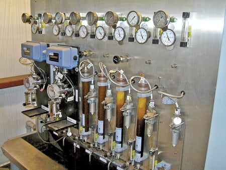
Many plants have common problems with the same kinds of water sample panels and on-line analyzers. Although every site and sample panel is unique (Figure 3), there are some basic tips and tricks that can be used to address many of those problems. (For the larger context of this issue, see "Maintaining water sample panels improves plant availability.")
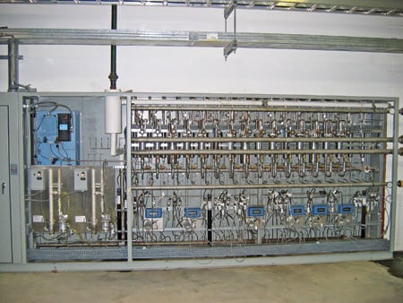
3. Where the action is. The back of a typical sample panel. Courtesy: Nalco
High-purity pH analyzer drift. High-purity water (condensate, boiler feedwater, demin water) has low ionic strength. On-line high-purity pH analyzers often use salt bridges or reservoirs to boost a sample’s ionic strength. Figure 4 shows one popular high-purity pH analyzer configuration that includes a salt reservoir. It’s important to replace salt bridges/reservoirs before they are exhausted. Most manufacturers recommend replacing them annually.
4. Worth its salt. A high-purity pH analyzer equipped with a salt reservoir. Courtesy: Nalco
It’s also important to remember that most high-purity pH and conductivity analyzers provide more-accurate and -repeatable readings than wet tests of the same high-purity sample. But this sensitivity has a downside: Contact with air changes the pH and conductivity of high-purity samples.
In addition, bench-top pH meters must be calibrated specifically for high-purity water pH measurement. Ensure that your meters either are calibrated with low-ionic-strength buffers or that an ionic-strength booster is added to samples before analysis. It’s best to use two bench-top pH meters: one for high-purity waters and one for low. The high-purity instrument should never be used to measure the pH of low-purity water.
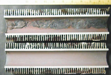
High cation conductivity. Exhausted resin is the most common cause of high cation conductivity (Figure 5). Solving the problem is as simple as replacing the resin before it’s depleted. Plants should maintain a full set of replacement resin on site that’s ready for use. The best practice is to maintain the same number of replacement resin sets (or resin volume) in inventory as there are installed cation columns.
5. Shoot the moon. High cation conductivity caused by exhausted resin. Source: Nalco
Most of the cation conductivity resins in use are supposed to change color as they exhaust. Plant maintenance and chemistry personnel rely on this color change to indicate when the resin needs to be replaced. Unfortunately, sometimes the color change is subtle, or masked by the effect of a contaminant. For example, iron fouling can make a resin dark enough to obscure the change in hue. Other foulants can cause the resin to stop exchanging even if it’s not exhausted, again masking the color change. If the color of a resin does change, it should be replaced while at least 10% of the resin remains unexhausted.
As a rule of thumb, replace the cation resin any time the cation conductivity consistently reads higher than 2 µS/cm (microSiemens/centimeter). Cation conductivity should never consistently read greater than this value. Finally, for accurate readings of degassed cation conductivity, ensure that the heaters are energized or that nitrogen is flowing any time that sample is flowing through the cation column. The degassed reading is supposed to eliminate interference caused by carbon dioxide, but that’s only the case if the small reboiler heaters are energized or if the scrubbing nitrogen is being fed.
Unreliable or highly variable ORP. Oxidation-reduction potential (ORP) analyzers are some of the most difficult to calibrate and maintain, for several reasons. First, the probes themselves are subject to fouling and age rapidly. Most probe manufacturers recommend annual or biannual replacement even if the probe appears to be working correctly. Probe response tends to slow with age, and periodic replacement minimizes this problem.
Probe response can be verified by monitoring trends closely to ensure that the analyzer’s readings change as expected. Does ORP increase when dissolved oxygen increases? Does ORP decrease when dissolved oxygen decreases or when a reducing agent (like a passivator) is added?
To calibrate an ORP analyzer, carefully follow the manufacturer’s recommendations. ORP analyzers should not be offset to agree with dissolved oxygen data or other ORP readings. Offsetting ORP readings tends to throw off the calibration rather than improve accuracy. Instead, instrumentation and control personnel should perform a full calibration if an analyzer’s accuracy is suspect. Again, using the proper calibration procedure is essential. Calibration reagents can actually destroy the probe if they’re not properly applied and rinsed.
Finally, evaluate new technologies. New probe designs are in the pipeline and should be available within a year. The newer probes can actually monitor ORP without first cooling the sample. They promise significant improvements in responsiveness and accuracy.
Large deviations in low-range silica readings. This problem doesn’t occur at all plants, but it has at several. Many sample panels use the Hach 5000 silica analyzer for continuous analysis. This model is generally reliable, but it is calibrated with a 500-ppb standard—the lowest-level standard that Hach can supply. The problem is that most high-purity streams have less than 10 ppb of silica, so calibrating the analyzer with a 500-ppb standard would lower its low-end resolution. Some plants see negative silica readings or poor agreement between the wet test results and the on-line analyzer.
Fortunately, there’s a way to address this problem. Plants can create a custom standard (50 ppb is common) by diluting the standard Hach 500-ppb standard with good-quality demin water. Once the custom standard has been created, its concentration must be verified using a laboratory spectrophotometer to perform an ultra-low-range silica test on it. Perform the test at least three times and verify that the results read within 5% of each other. If they do, then average the three readings and write this value on the standard bottle. The Hach 5000 accepts custom standards; refer to the manual for the procedure. Enter the value of the custom calibration standard and ensure that the instrument is set for automatic calibration. The unit will calibrate using the new, lower standard and will provide better low-end resolution.
If readings continue to show high deviation with wet test results, closely inspect the reagent tubes for plugs or cracks and check the “pinch” valves for proper operation. The Hach manual provides detailed troubleshooting procedures.
Sodium analyzer calibration drift. Calibrating sodium analyzers can be very difficult. Because many plants lack the understanding or knowledge to do so, most makers of sodium analyzers offer calibration training. The written calibration procedure provided with the instrument is sufficiently convoluted to stymie even the most-experienced technician. Nalco and Calpine advise plant managers to pay for annual OEM training of operators and techs on the proper calibration of sodium analyzers; it can significantly improve the reliability and accuracy of readings.
Also bear in mind that sodium analyzers are notorious for losing accuracy during cycling operation or whenever they lose sample flow. Using demin water to maintain sample flow significantly eases maintenance.
Finally, many plants do not calibrate sodium analyzers at the manufacturer’s recommended frequency. Orion analyzers, for example, generate an error message after 30 days. Many plants continue to operate the analyzer even after receiving this alarm. Calibration drift is inevitable if monoethylamine is used as the buffering reagent. Drift may be minimized if diisopropylamine (DIP) is used instead. DIP is completely volatile, so there is no dilution of the reagent over time. Though this reagent change can minimize drift, sodium analyzers must still be calibrated at the frequency recommended by their manufacturer.
—Dan Sampson, (dcsampson@nalco.com) of Nalco Co.
PUMP MAINTENANCE
Qualifying rebuild shops
Routinely rebuilding old centrifugal pumps to their original specs makes no sense, given advances in pump rebuilding technology and inevitable changes in system performance over time. A qualified independent rebuild shop with modern design tools and experienced personnel can verifiably offer high-quality upgrades that improve both uptime and efficiency consistent with current system performance requirements.
Consolidation in the pump industry (Figure 6) is another reason to consider using a rebuild shop. Some pump makers now lack the same level of engineering competence they once had. There have been instances of vendors “downsizing” or “right-sizing” their inspection department into oblivion. In these cases, the company’s customers pay the price in unexpected pump downtime and even unit outages.
6. Fewer options. Consolidation within and among major pump manufacturers continues. Courtesy: Heinz P. Bloch, PE
The qualified pump rebuild shop has both the tools and the experience needed to define a scope of work that goes beyond routine rebuilding or performance upgrading. It takes a lead role in defining the scope of work, and it begins by impressing on customers that a reasonably accurate definition will be possible only after a thorough incoming inspection. This task entails logging (on both a paper and a computer document) details such as the pump’s type and model, the location of its plant and its type of service, its direction of rotation, and all of its O&M data.
Once a shop has inspected a pump and logged its salient details, the next steps are to describe its general condition and to propose in greater detail the work needed to rebuild or upgrade it. This process is called the condition review.
Condition reviews include taking photographs of as-received equipment and close-up shots of parts and components of special interest. The sizes of end floats and lifts and other detailed measurements are placed on a dimensional record form both before and after dismantling the pump. Components are marked or labeled, and hardware is counted and cataloged. Bearings, bushings, and impellers are removed. Blasting with beads or steam or another cleaning method is proposed and listed, along with an agreed-on completion date for this preliminary activity.
Nondestructive testing (NDT) is the next possible step, and it should be used whenever appropriate. A good pump rebuild shop will issue a form that identifies the chosen inspection method, perhaps using a liquid dye penetrant or magnetic particles. Although space limitations preclude a detailed discussion of NDT inspection here, competent pump repair shops recognize its importance and usually emphasize its necessity to pump owners.
Some pump condition reviews also include taking readings of electrical run-out at eddy current probe locations and measuring the shaft’s balance and residual unbalance and the balance of individual impellers. The responsibility for performing these inspections, acceptance criteria, condemnation limits, and other items of interest are listed on a form. Ultimately, some inspection results also are documented on this form; others go on separate forms.
Recall that the term “form” was defined to include both hard-copy and computer documents. With this in mind, it should be clear that there will be a need to make a transition from documents that define the initial scope of work to documents that deal with material certification, documentation of as-achieved (or as-built) dimensions, the service fitness of auxiliary components, or repair quality. Nonetheless, it should suffice to say that defining the scope of work and the incoming inspection and condition review are important first steps in the pump repair process.
In future articles, we’ll explore actual case histories of pump repairs, both good and bad, and explain how to work with a repair shop to ensure that it returns an overhauled pump with a new lease on life.
—Heinz P. Bloch, PE (hpbloch@mchsi.com) of Process Machinery Consulting.