Recent advances in water laboratory instrumentation—from improved sample conditioning to advanced online instruments—have reached the market. Here’s a look at the equipment you’ll find in the best-equipped power plant laboratory this year.
Steam cycle chemistry analysis begins with the sampling methods and ends with the analytical instruments used. These tools don’t last forever.
The average lifespan of a sample and analytical panel is 10 to 15 years. After that, online analyzers degrade, become less reliable, and replacement parts become increasingly difficult to source. If your power plant was built in the 1990s and you haven’t already overhauled your sample and analytical panel on the unit, you are probably long overdue for an upgrade. The sampling system should also be overhauled if you are receiving a hot sample or if the sample stream is arriving as a trickle. A state-of-the-art analyzer that’s provided with poorly conditioned samples is of little help. Quality sampling and analysis are critical for monitoring power plant chemistry.
There have been many innovations in making sample streams more consistent and representative. Instruments that monitor a power plant’s water and steam chemistry have made significant advances over the past few years, especially by lowering the detection limits for critical impurities. The net result is more precise water and steam chemistry and fewer chemistry-related failures caused by corrosion and contamination when the monitoring is heeded and contamination is prevented.
Recent advances are the result of the new normal: Most utilities no longer have staff trained in chemistry at the plant 24/7 to monitor critical steam and water cycle parameters. Additionally, more of the analyses must be automated, instead of using grab samples, in order to achieve real-time results with the required accuracy.
An accurate understanding of your plant’s steam cycle chemistry depends upon following the current guidelines for collecting and processing water and steam samples and being aware of the latest advances in online analyzers.
Follow the Leaders
The recommendations of the Electric Power Research Institute, American Society of Mechanical Engineers, and, most recently, the International Association of the Properties of Water and Steam (IAPWS) require online continuous analysis of all parameters that are critical to minimizing corrosion and deposit formation in the boiler or turbine. Each of the water chemistry parameter limits set by these industry organizations links directly back to specific failure mechanisms in the steam and water cycles. These published recommendations give us guidance as to the parameters monitored and their concentration levels. This information also tells us the type of equipment and the accuracy requirements of equipment purchased for the plant water laboratory. For example, the IAPWS recently published recommendations for the concentrations of key parameters used to monitor the steam cycle (Table 1).
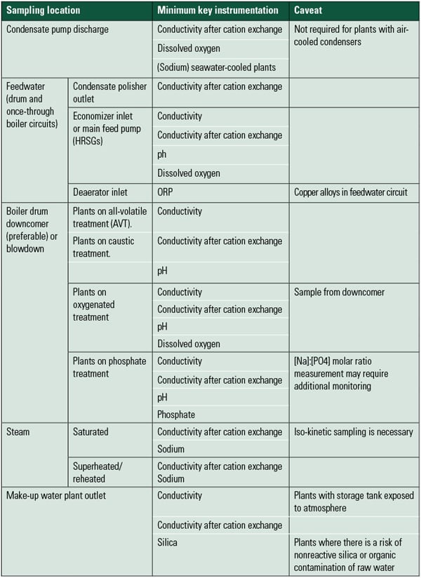 |
| Table 1. Summary of minimum key instrumentation requirements for power plant water analysis. Source: IAPWS Technical Guidance Document: Instrumentation for Monitoring and Control of Cycle Chemistry for the Steam-Water Circuits of Fossil-Fired and Combined-Cycle Power Plants, September 2009. |
In the past, the concentration of some of the critical water treatment contaminants that can damage the turbine could not be measured directly at the part per billion (ppb) levels, so indirect measurements were substituted. For example, the familiar cation conductivity analyzer has been a required parameter by turbine manufacturers because it provides a simple and robust means of indirectly detecting ppb levels of chloride and sulfate. Another indirect measure is sodium. Sodium ions per se don’t damage turbine components, but sodium hydroxide does. We can’t measure the ppb levels of hydroxide, so we measure sodium instead, and we assume that all of the sodium in the steam is there in the form of caustic (sodium hydroxide) as a worst case.
But these indirect measurements can be fooled by other contaminants that may not be harmful. For example, dissolved carbon dioxide in the form of bicarbonate will raise cation conductivity, though it has been shown that the dissolved carbon dioxide in the steam is not harmful to the turbine. During commissioning, this has caused many a battle between the owner and turbine manufacturer about the warranty and how reasonable or unreasonable the cation conductivity limits are.
Start at the Source
As the power industry continues to pursue lower and lower detection limits, the critical importance of good sampling and sample conditioning is often overlooked. The most accurate and reliable instrumentation cannot provide good information on a bad sample. Also, learning that there is significant contamination in the boiler 30 minutes after the boiler water pH has dropped is unacceptable. Good chemistry control starts with good sampling (see “Maintaining Water Sample Panels Improves Plant Availability,” March 2008 in the POWER archives at https://www.powermag.com).
Progress has been made in sample conditioning procedures and system design to ensure that the sample that reaches the analytical instrument accurately represents what was really going on at the sample point in the steam cycle, within seconds after the sample leaves the steam line or drum (Figure 1).
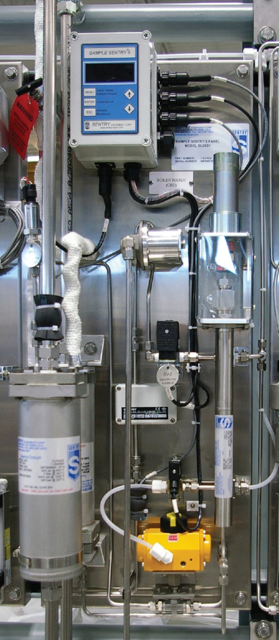 |
| 1. Smart sampling. A state-of-the-art sample conditioning system provides a constant sample flow regardless of supply pressure at the recommended velocity. A fully automated sample conditioning system, as shown in the photo, will improve sample accuracy and keep your chemistry within EPRI-recommended guidelines. Courtesy: Sentry Equipment Corp. |
A properly configured sample line and sample conditioning panel follows several well-accepted design practices (see sidebar).
Most sampling problems begin at start-up, when particulates in the equipment can restrict flow or even plug up the sample lines and pressure-reducing valve. Provisions to safely flush out the sample line(s) during start-up are important to maintaining a good sample. Even with these precautions, small amounts of particulates can accumulate in and behind the pressure reduction value or variable pressure reducing element (VREL) valve. These can be manually flushed out by temporarily opening the valve slightly to increase the pressure (and flow) in the line.
The best design uses a VREL valve that monitors total sample flow and pressure and automatically adjusts the sample flow for the upstream pressure. As particulates build up on the valve or upstream in the sample line, sample flow drops. The automated valve senses the sample flow decrease and opens the VREL valve, which flushes out the particulates. It also shuts off the sample completely when the pressure on the line drops below a set limit (when the unit is off-line) and opens when the unit comes up to pressure. This is particularly helpful on units that start and stop frequently or that start when lab personnel would normally not be present to manually flush the sample lines.
This is not to say that all chemistry parameters need to be monitored and controlled on a continuous basis. There will always be a subset of parameters for which testing once a shift, or even once a week will be sufficient. But the combination of the availability of online instrumentation and reductions in the number of plant staff, particularly specialists such as trained lab chemists, will continue the push toward more online monitoring.
Important Monitor Trends
There are a number of large trends emerging in the world of steam and water sampling that cross instrument and electronics manufacturer boundaries. A few of these are mentioned below.
Integrated Sensors. Integration of the measuring circuit, calibration and diagnostics, memory, and analog-to-digital conversion into a single, compact electrochemical sensor is a rapidly growing trend.
For example, consider the familiar pH probe. When measuring the pH of a solution, the interaction between the probe and the sample generates a millivolt signal. This signal is sent to the meter, where it is interpreted and the pH is displayed. When the pH meter is on a lab bench, the distance between the probe and the meter is typically only a few inches. However, in a power plant, a pH probe may be located on a sample line coming into a central sample panel that may be located hundreds of feet away from the monitor, which can cause signal degradation and incorrect pH readings. Also, if the cable is run adjacent to other instruments or electrical sources, additional signal noise and interference is possible. Usually, the manufacturer will specify the maximum distance between the probe and the monitor to minimize that interference, particularly with conductivity meters.
With an integrated sensor, all the signal processing is done on a microprocessor located inside the probe. The signal leaving the probe is a digital signal that can be sent as far as required without significant signal loss or interference. Furthermore, because the calibration information is also on the chip, the probe can be calibrated in the controlled setting of a laboratory or maintenance shop, disconnected, and then installed in the field. Once installed, the probe is ready to go.
Besides pH, instrument manufacturers are also making integrated conductivity, oxidation reduction potential, and dissolved oxygen probes (see “How to Measure Corrosion Processes Faster and More Accurately,” May 2009). Some of these sensors are “smart” enough to monitor themselves and predict the need for maintenance. For example, Mettler-Toledo Thornton’s Intelligent Sensor Management product line stores the calibration data collected in the lab on a chip in the sensor. This approach ensures that the latest calibration data for the field-mounted instrument is always used.
Another advantage of integrated sensors has been an expanded range of linear operation. A single model of an integrated conductivity probe can be used for everything from the condensate to the cooling tower. The user no longer has to stock different probes for different applications nor has to make sure that the cell constant and conductivity range match that application.
Automatic Calibration. More online instruments are incorporating a completely automatic calibration sequence using vendor-supplied standards. This is especially worthwhile where the calibration process requires an extended period for equilibration to low concentrations such as with sodium and silica measurements. The calibration sequence can be initiated by an internal timer. The analyzer then stores this information for later retrieval. For these instruments, service consists mainly of replenishing calibration standard solutions and reagents.
Wireless Data Transmission. Wireless capability is available in all manner of devices, so why not a pH meter or sodium analyzer? As the reliability of signal transmission and security improves, and battery life and sensor costs decrease, expect to see more of your online analytical data available on your smart phone or other wireless device. Wireless data transfer is already being used at plants to monitor data taken at remote locations, such as plant water outfalls.
Analyzer Improvements
Beyond the general trends mentioned above, a number of analyzers have been significantly improved or replaced with better technology. Some of these have been around for a few years, but they may not yet be common in the North American power plant.
High-Purity pH: Measured, Calculated, or Both. Determining the pH of high-purity condensate or deionized water can be frustrating to near impossible with a conventional pH probe or a benchtop meter. The primary reason is the extremely low number of ions in the sample, which are necessary to “complete the circuit” across the reference junction in the probe. Add to this stray currents and gas (ammonia and carbon dioxide) exchange between the sample and the atmosphere, and what you get is a pH reading that never settles out but can drift over time. This is a situation where the pH as measured by the benchtop meter is rarely as accurate as a properly configured online pH analyzer.
The manufacturers of online pH meters for the power industry have developed specialized pH probes for high-purity water samples, particularly when measuring condensate, feedwater, and boiler pH. These specialized probes share a number of characteristics. If you are revamping an old sample panel, or building a new plant, you will want to be sure that the pH probes you order have the following characteristics:
- A low-volume stainless steel flow chamber that is earth-grounded. This minimizes stray electrical signals and potentials caused by the sample streaming past the probe.
- A low, constant flow rate must be provided to the probe.
- A flowing junction reference electrode that continuously supplies a small amount of potassium chloride solution at the junction between the reference electrode and the sample must be provided. Because the junction is continuously leaking potassium chloride, there must be a reservoir of this solution that must be occasionally replenished.
- If you can’t rely on a constant-temperature sample, then you must use a meter that allows not only a standard temperature sample (25C) but also one that automatically compensates for the actual probe and solution temperature. The typical correction for an ammonia-based feedwater is –0.032 pH/C, though this factor may depend on specific conditions at each power plant.
When You Can’t Measure pH, Calculate It. Even with all these measurement improvements, samples with very low conductivity may still be very difficult to accurately measure. For these tough situations, instrument manufacturers have developed equipment that uses specific conductivity, cation conductivity, and some assumptions about the sample to calculate the sample pH. Calculated pH meters have been in use in Europe for some time, but they are still new to many in North America.
In order to accurately calculate pH, you must first make several important assumptions about the sample. First, you must assume that there is very little else in the sample besides water and a trace of ammonia—a good assumption for most condensate and feedwater samples in high-pressure steam units. Second, you must make an assumption regarding the nature of the remaining anions in the sample: that the majority of those are hydroxide (from the ammonia) with much smaller amounts of dissolved carbon dioxide and very low levels of chloride and sulfate.
If we assume these assumptions are correct (and under normal conditions they are), the pH can then be calculated using a relationship based on the specific conductivity of the sample, because it is proportional to the ammonia concentration. As the sample passes through the cation column, ammonium ion is exchanged for hydrogen combining with the hydroxide to make pure water. Any remaining anions in the sample produce the cation conductivity reading. The cation conductivity value is then used to generate a factor that reduces the calculated pH proportional to the value of the cation conductivity. The algorithm cannot properly calculate pH if the cation conductivity of the sample is higher than the specific conductivity. This occurs when there is a significant concentration of chloride and sulfate ions in the sample.
Furthermore, it may be important to differentiate between a pH depression caused by dissolved carbon dioxide from other anionic species in solution. Degassed cation conductivity can be used to calculate the amount of carbon dioxide in solution. At least one manufacturer, Mettler-Toledo Thornton, can display the measured pH; calculated pH; specific, cation, and degassed conductivity; and calculated carbon dioxide on a single monitor.
Direct Measurement of Chloride and Sulfate. Ion chromatography (IC) was developed in the mid-1970s and quickly became the analytical tool of choice for measuring low levels of anions and cations in aqueous samples. It is used in many industries and settings, from environmental samples to pharmaceuticals. It has also found a niche in the power industry.
For those unfamiliar with the method, IC is part of liquid chromatography with an aqueous mobile phase (eluent) and a stationary phase. Think of IC as a very small cation or anion vessel in a demineralizer system. We know that in a demineralizer, certain ions (sodium in a cation vessel and silica in the anion) pass through the bed more quickly than others. The speed depends on the chemical interaction of the cation or anion resin beads, which hold on to some ions more strongly than others.
The analytical columns for IC contain nanobead-agglomerated ion exchangers very similar to those in a conventional demineralizer cation and anion vessel. Behind the analytical column is an suppressor system (used to eliminate background conductivity) and a conductivity detector. IC can identify specific ions because, under a given set of conditions, each ion is always retained on the column for the same amount of time. The IC can quantify the amount or concentration of particular ions because software calculates the increase in conductivity as the ion elutes from the column and compares that value to a set of standards.
In steam generating systems, IC has been used for many years to detect ppb and even part per trillion levels of ions, such as sodium, calcium, and magnesium. But more importantly, IC can separate and quantify inorganic anions such as chloride, sulfate, and organic acid anions—including acetate, formate, and glycolate—and do all of this in the same chromatographic run.
Often during commissioning, the owner, contractor, and steam turbine supplier are at odds because the cation conductivity of the steam exceeds the normal operating limit for the steam turbine. Allowing this steam to flow through the turbine would void the warranty. The problem for the owner is that it is difficult and expensive to continue to blow steam until the cation conductivity comes within specifications. Also, cation conductivity can be fooled by carbonate or traces of organic compounds left over from start-up. How could you be sure that the contamination was from chloride or sulfate? One solution that has often been used is to set up IC, at least during the commissioning period, as the final arbiter of the purity of the steam.
The downside is that conventional IC has been manpower-intensive to set up and calibrate. Finding a source of ultrapure water and preventing contamination while preparing the standards has become increasingly difficult. There are also plenty of opportunities for small errors in the preparation of the gallons of eluents that were required to run the unit. Small variations in the equipment and operator technique could affect the accuracy of the analysis. Needless to say, only a few power plant laboratories have been able to dedicate the time and personnel to get this instrument up and running to analyze boiler and condensate samples with any regularity.
Some recent improvements to IC have solved these problems, making the new equipment far more power plant–friendly. One important advancement was eliminating operator handling of the eluents; the eluents can now be electrolytically generated. Eluents containing the correct amounts of hydroxide (for anions) or methanesulfonic acid (for cations) are generated automatically with the help of an eluent cartridge.
The second improvement is the use of capillary columns instead of the standard analytical columns of the past. This advancement is analogous to capillary columns in the world of gas chromatography. These capillary columns are capable of providing the same separation of the ions as larger-bore columns, but they only use microliters of sample and eluent to do so. Combined, these two technologies make a system that:
- Detects single-digit ppb levels of anions such as chloride, sulfate, acetate, and formate.
- Is always on—ready to run an analysis any time, without any warm-up.
- Requires changing of the eluent cartridge every 18 months; no more chemical mixing of eluents is required.
- Generates very little liquid waste—about 5 liters per year.
If you use an amine in your feedwater or an organic additive in the makeup water, cation conductivity cannot provide accurate readings of low levels of chloride and sulfate, which are required to protect the turbine. If so, IC is the technology of choice.
New Competitor: Capillary Electrophoresis
Until recently, only IC could detect multiple anions or cations in a single run at the ppb levels needed by steam cycles. There have been specific ion electrodes for chloride, for example, but IC is alone in its ability to produce both a chloride and sulfate analysis on the same run.
Another emerging measurement technique is gel electrophoresis, used for many years to separate DNA into its various base pairs. The simple analytical premise is that when you apply a voltage, molecules will pass at different rates through a medium, based on their affinity for the charge at the far end of the plate.
A similar process can be applied to inorganic ions. Capillary electrophoresis is currently under development by Advanced Microlabs of Fort Collins, Colo. A very small sample of known volume is injected into a capillary channel. The channel is flushed with a continuous supply of an electrolyte buffer. The ions separate as they pass through the channel and past a micro-conductivity meter at the end of the channel. This meter senses the change in conductivity as the ions are eluted out of the channel. The online instrument will take a continuous sample and filter a small portion of it through a 1-micron filter before sending it to the electrophoresis module. It takes a little more than 2 minutes for the sample to traverse the capillary electrophoresis channel and approximately 5 minutes between sample cycles. This equipment is designed to be continuously (every 5 minutes) sampling, analyzing, and producing data (Figure 2).
 |
| 2. The capillary electrophoresis module. The thin S-shaped line in the middle of the “circuit board” is the ion channel through which the sample passes. The module can analyze levels of chloride and sulfate in parts per billion. Courtesy: Advanced Microlabs |
The manufacturers of the equipment anticipate that a module will be in the analyzer for approximately one month and then be changed out with a new one. They are able to achieve detection limits of less than 1 ppb not only for chloride and sulfate, but soon should also be able to achieve these limits for silica, thereby pushing the limits of the classic spectrophotometric analyzer. Cations that can currently be determined include sodium, calcium, and magnesium; others, such as ammonium ion, are expected the near future.
To date, Advanced Microlabs has been working with nearby Colorado utilities to develop this process specifically for a utility market. Test units are currently in place, and Advanced Microlabs anticipates commercially available units in the second quarter of 2012.
Dissolved Oxygen Probes —Using Light
For many years, the most common dissolved oxygen probes were based on the amperometric principle. Dissolved oxygen in the sample first passed through a gas-permeable membrane into a chamber filled with an electrolyte. Here the oxygen would be consumed at an inert metal cathode, while a large anode was converted to an oxide, completing the circuit. The amount of dissolved oxygen in the sample was related to the amount of current generated by the probe by the electron transfer from the cathode to the anode.
There were a number of difficulties with the measurement approach for an online environment in a power plant, usually with the membrane. Over time, the outside of the membrane would foul with iron oxide, slowing the response of the probe. Also, because the probe would use the oxygen in the sample for the determination, the probe was very dependent on sample flow rate for a correct analysis. Replacing the membranes on some probes required dexterity and a little luck. Occasionally, electrolyte also needed to be replaced and the probe had to be refurbished. Better membrane replacement systems were developed by some manufacturers. Some even offered a factory-refurbished probe replacement service.
A recently introduced dissolved oxygen probe operates on a completely different technology: A light source is used to determine the dissolved oxygen concentration. The principle of operation is that a blue light source illuminates an area coated with a dye that produces a red fluorescence. As the sample passes by this area, any dissolved oxygen in the sample causes a phase shift in the response time of the red fluorescent light that is proportional to the amount of dissolved oxygen in the sample (Figure 3).
 |
| 3. Glowing report. According to Hach, “the oxygen sensor is made up of a clear, oxygen impermeable hard substrate. An oxygen sensitive luminescent dye, along with a scattering agent, is pad-printed on the substrate. A final overlay of dark pigment is added to prevent stray light from entering the measurement cell. The luminescent dye emits red light when exposed to blue light. The scattering agent distributes the emitted light throughout the sensor matrix and contributes to the opacity of the sensor. Pulses from a red LED serve as an internal reference. The duration of the luminescence is proportional to the concentration of dissolved oxygen in the sample.” Next-generation luminescent sensors will measure dissolved oxygen in parts per billion. Courtesy: Hach Co. |
This technology was developed by Hach in 2006 and has been used successfully in many applications that operate at higher (parts per million) dissolved oxygen levels. However, the probe and electronics have been further improved so that now it can operate in the low ppb range required by steam cycles.
Head-to-head testing of a luminescent probe against an electrochemical Orbisphere dissolved oxygen analyzer (Orbisphere is now also owned by Hach) showed excellent correlation at levels in the single-ppb range in an actual power plant setting. Obviously, the membranes or electrolytes with a luminescent probe are not accessible, so the probe requires far less maintenance than conventional dissolved oxygen probes, and the maintenance required is very simple.
Special thanks to David Gray of Mettler-Toledo Thornton, Joachim Weiss of Dionex Corp., Vickie Olsen of Hach, and Uwe Michalak of Advanced Microlabs for their help in the preparation of this article.
— David G. Daniels (david_daniels@mmengineering.com) is a principal of M&M Engineering and a contributing editor to POWER.