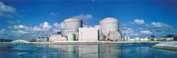
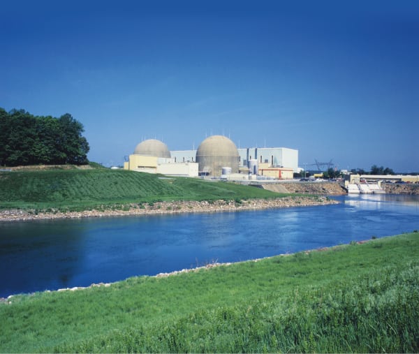
The 1,150-MW Fermi 2 Power Plant, located on the shore of Lake Erie, consists of a single operating unit based on the GE boiling water reactor design. The plant entered commercial service in January 1988, making it one of the last nuclear power plants to enter service in the U.S.
Fermi 2 may be young when compared with the other 103 U.S. nuclear plants, but age is relative; upgrades and renovations of operating plants to extend their lives have become the norm. In the case of Fermi 2, during the system analysis conducted as part of the plant’s recent power uprate evaluation, DTE Energy concluded that the plant required upgraded moisture separator reheaters (MSRs). Sounds simple on paper, but removing two 300-ton, 115-foot-long vessels in one piece and replacing them with new MSRs is much more difficult in practice. In fact, it had never been done.
Long-term teams
That Fermi 2would take on this challenge is a testament to a strong partnership. Washington Group International has been providing nuclear support services through an alliance with DTE Energy for more than 15 years. The alliance provides DTE Energy with engineering expertise and construction resources for major capital improvement projects; in return, Washington Group receives incentives for developing unique design solutions that reduce construction costs and for delivering other value enhancements for plant operating improvements.
Scott Reeder, vice president-DTE Alliance for Washington Group, outlined the scope of the arrangement: “Our contract under the alliance ties our financial success to the successful operation of the plant. As a result, our employees have continually demonstrated exceptional ownership of the Fermi plant’s performance results and, together with the employees of Detroit Edison, have demonstrated exceptional teamwork. The planning and execution of the MSR replacement project are evidence of this effective teamwork.”
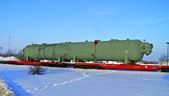
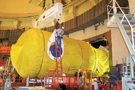
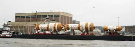
A team consisting of representatives of the Fermi 2 staff and Washington Group was formed to manage the MSR replacement project upon its approval in January 2003. Pre-outage work at the plant began in September 2005. The MSRs arrived on site in December 2005 (Figure 1) and were lifted to the turbine deck elevation by a heavy-lift tower that spanned the railroad tracks (Figure 2). They then were transferred to the plant by overhead bridge cranes and moved to in-plant staging locations (Figure 3). Outage work began on March 25, 2006, and was completed on May 2. The MSR project was a part of a large refueling outage during which Washington Group undertook a number of other challenging projects.
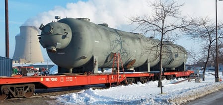
1. Oversize load. A new moisture separator reheater (MSR) arrived at the project site during freezing winter temperatures. It spanned two rail cars. Courtesy: Dave Mitchell, DTE Energy photographic services

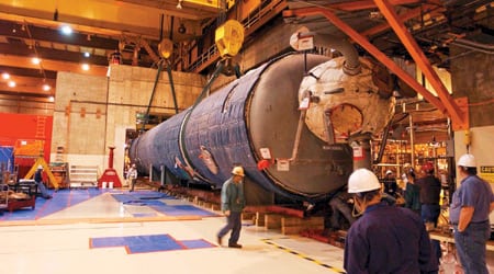
2. Heavy hitter. One of the two new MSRs being lifted to the temporary construction access panel and onto the turbine deck for staging. Courtesy: Dave Mitchell, DTE Energy photographic services
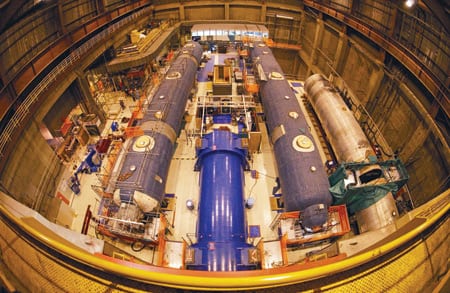
3. Bird’s eye view. The turbine deck with the old moisture separator reheater (far right) and the new MSRs on each side of the generator. Courtesy: Dave Mitchell, DTE Energy photographic services
Weather conditions also presented a challenge. Construction of the heavy lift tower and movement of the vessels occurred in unusually cold and windy conditions, with temperatures in the single digits and the wind chill well below zero.
Create a new critical path
The MSR separates moisture from high-pressure turbine exhaust and reheats the steam for the low-pressure turbine. At Fermi 2 the MSRs are located deep within a concrete shielding structure and are highly integrated with the plant’s piping network. That meant the team’s first order of business during the planning process was to determine how the old MSRs would be removed and the new ones shoehorned into place.
The traditional approach to extracting and replacing original equipment MSR vessels requires extensive removal of plant equipment and structures and an extended plant outage—not an option the team would consider. The standard approach—and the one used during original plant construction—was to install each of the MSRs in two half-sections, join the two sections by welding, and then install piping to fit. The team was sure a faster and cheaper procedure was possible.
However, in considering its options, the team realized it was time- and cost-prohibitive to remove existing piping and that the existing MSRs were housed inside reinforced concrete structures. The project was further complicated by the fact that these components were within the radiological-controlled boundary of the plant and thus inaccessible when the plant was operating. Finally, the dimensions of the access area constrained the size of the new MSR. Tolerances were tight no matter which option was considered.
A little outside-the-concrete-box thinking led to a unique and previously untested one-piece installation approach that was the team’s best opportunity to stay within its 35-day outage window. The plan also would save over $10 million in replacement power costs—the penalty for extending the outage, as was originally thought necessary.
Executing the plan, however, required the team to make a series of carefully choreographed moves: move the MSRs from the fabrication facility in Oklahoma to the plant site in Michigan, move these large components within the plant with access clearances of less than 2 inches (Figure 4), and then move the vessels to their final resting place within a 1/8-inch tolerance.
4. Tight squeeze. A new MSR begins its trek through the reinforced concrete wall with only 2 inches of clearance. Courtesy: Dave Mitchell, DTE Energy photographic services
Virtual toolbox
The plan was innovative and certainly cost-effective, but the obstacles to success were formidable. The team required months of painstaking planning for every step of the project. For example:
- First, the as-built status of existing plant equipment was meticulously mapped using laser surveying technology.
- That data was then translated into a 3-D design software package to enable the team to plan vessel movements within the allowable tolerances.
- A virtual construction plan was developed with 3-D animation that simulated the heavy rigging path.
- Next, design data and laser surveying tools were used to determine the exact dimensions required for the new vessels, including nozzle locations for piping up to 48 inches in diameter. The same virtual tools were used to confirm that the vessels could be maneuvered around existing plant equipment.
Finally, the team was convinced that a one-piece replacement approach was, in fact, possible.
The outage began with removal of the old vessels, which required cutting and machining dozens of piping connections and removing structural platforms. The vessels were then jacked from their foundations and removed from their cubicles by two rail and hydraulic slide systems.
Close tolerances
Installation of the new vessels required a full array of specialized equipment not normally encountered during a typical plant outage. For example, a special rail car was adapted to move the new vessels from Oklahoma to Michigan; a modular lift tower and integrated slide system was designed and erected at the site to move the new vessels from the rail car up to and inside of the power plant; and a unique cantilever lifting beam was used to remove large concrete wall sections to provide access for the new vessels. In addition, a specially engineered rigging path addressed the available 2-inch clearance and the need to lift the new components over the top of the generator.
Once the MSRs were inside the plant, the same hydraulic slide system used to remove the old vessels was used to ease the new ones into their cubicles to the exact location required. The vessels were a perfect fit with the existing plant piping, and the 800 pipe welds were completed without incident (Figure 5). Structural platforms were modified or replaced, and instrumentation and pipe insulation was installed. Plant shielding was then restored. Finally, the construction opening was repaired.
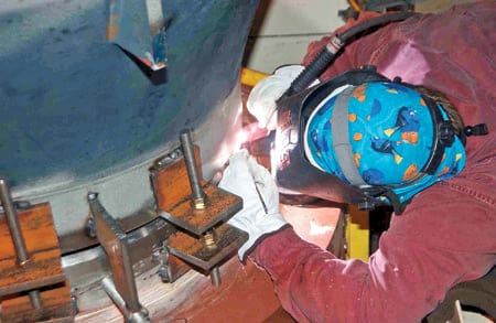
5. Perfect zero. The MSR project was completed early and with a perfect safety record. Courtesy: Dave Mitchell, DTE Energy photographic services
A tight team
“Washington Group is a valuable partner at our Fermi plant,” said Douglas Gipson, who is recently retired but was executive vice president and chief nuclear officer for Detroit Edison during the project. “The core values of our two organizations are well aligned. The Washington Group site team has delivered best-in-class safety results and has demonstrated outstanding ownership of our business results. Together we have employed exceptional teamwork in support of the plant.”
During the outage Washington Group employed more than 950 craft and staff workers. The MSR project was completed with no lost-time and no OSHA recordable injuries. This is just about the only time a score of 0.0 means you are a winner. That’s a safety record any contractor or plant manager would envy.
This project demonstrated that exceptional planning and teamwork, plus a little innovation when challenged with a first-of-its-kind project, will achieve best-in-class results. Kudos to the entire project team for a job well done.