Compared with other solid fuel–fired plants, the systems and components required for handling and processing biomass appear quite familiar, but important fuel differences must be considered. A successful biomass plant design must provide flexibility for handling the expected wide range of biomass fuel properties and characteristics.
Power plant owners and developers have multiple ways to include biomass as a fuel in their fleets. Cofiring—adding biomass generation to existing coal-fired plants—is a relatively inexpensive option. For large units, the simplest approach is to cofire biomass with coal. (For an example, see “OPG Charts Move from Coal to Biomass,” April 2010 in POWER’ s online archives at https://www.powermag.com.) Biomass can also be added to a plant that has smaller, older, inefficient coal-fired units: One or more old units can be replaced by a modern, efficient boiler that is designed to best utilize solid fuels, including biomass. Greenfield plants are a third option, but they take more time to bring online and obviously involve additional siting complexities.
Whichever option a plant owner chooses, designing a plant, or its retrofit, with the special characteristics of biomass in mind is critical for successful use of the various forms of this renewable fuel. Those characteristics affecting plant design are the focus of this article.
The EU Cofiring Experience
The European Union (EU) has set firm goals for renewable energy consumption, and all member states are expected to supply 20% of their energy requirements by 2020 from sustainable forms of energy. Those renewable options include wind, landfill gas, and biomass; solar, geothermal, and wave power are also expected to contribute small amounts.
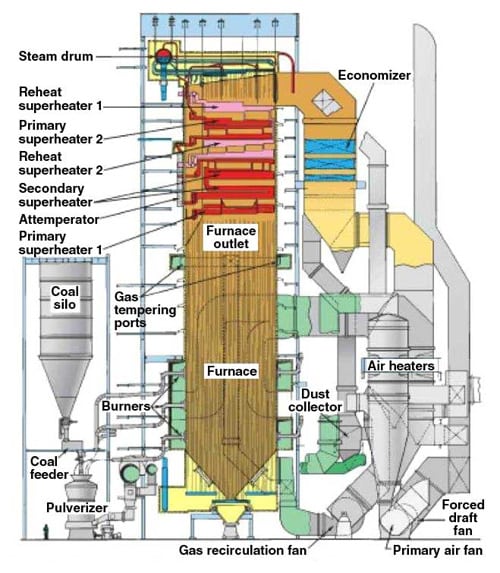
Because of the EU’s renewable energy requirements, some European coal-fired plants have implemented or are developing programs that will add biomass to their fuel mix. In the United Kingdom (UK), what appears to be the largest cofiring project was recently brought online by Drax Power. Its 4,000-MW coal-fired Drax Power Station in Selby, North Yorkshire, is the largest coal-fired station in the UK and provides enough power to meet 7% of the UK’s electricity needs. (See “Drax Offers Model for Cofiring Biomass,” July 2010.) Drax Power began experimenting with a system that blends biomass with coal, using the existing emergency coal reclaim hopper. Based upon the success of this project, Drax Power recently completed an £80 million ($150 million) direct biomass injection system. Together, the 100-MW blending and the 400-MW direct injection systems provide 500 MW of biomass generating capacity (Figure 1).
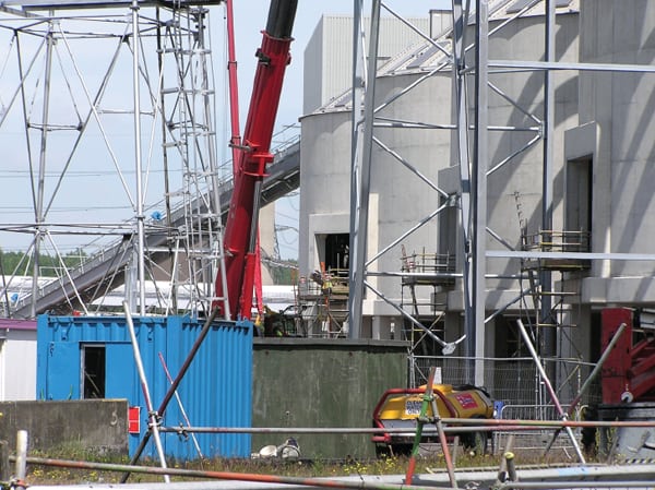 |
| 1. Biomass is big in the UK. The 4,000-MW Drax Power Station recently completed a retrofit that allows it to blend biomass with coal using the existing emergency coal reclaim hopper. Together, the 100-MW blending and the new 400-MW direct injection system provide 500 MW of biomass generating capacity. This photo shows the handling and storage area of the biomass cofiring system during construction. The facility uses wood pellets that are delivered by rail. Bottom dump rail cars are unloaded, and the pellets are stored in four silos. The wood pellets are reclaimed and conveyed to a fuel feed bin and then pneumatically conveyed and injected into the combustor. Courtesy: Energy Associates |
Cofiring in a Utility Boiler
Many utilities have a fleet of existing multi-unit coal-fired power plants. The easiest way to add biomass to the fleet is to adapt those existing plants to burn biomass. Although doing so requires plant additions and modifications, compared with starting from scratch, modification for cofiring is a relatively low-cost option. This can be practical when the amount of biomass available is relatively modest. Approximately 4% to 5% biomass can be blended with the reclaimed coal, especially if the unit has spare mill capacity. At increased percentages of biomass, direct firing is advantageous. In fact, boiler capacity can actually be improved by biomass cofiring when unit generation is limited due to wet coal.
Beginning in 1996, the Electric Power Research Institute and the U.S. Department of Energy (DOE) began a biomass cofiring research program that continues today. Demonstration projects were conducted at several pulverized coal (PC) and cyclone plants. The program tested biomass cofiring with heat input rates up to 10%. The amount of biomass that was cofired varied with the method of biomass feeding; it was either blended directly using the coal reclaim system or separately injected directly into the furnace.
Normally, adding biomass to the fuel matrix decreases boiler efficiency. This decrease in efficiency is a function of the biomass characteristics and unit design parameters. The dominant reasons for this decrease are the fuel’s higher moisture content and the hydrogen/carbon atomic ratios in biomass, as compared with those of coal. The latent heat of vaporization for moisture, and the pyrolysis of oxygen and hydrogen components of biomass into moisture, have been shown to reduce boiler efficiency by 2% at the 20% cofiring level on a mass basis.
Air emissions are also affected by cofiring biomass. Biomass cofiring typically reduces SOx and NOx emissions due to the biomass fuel’s lower nitrogen and sulfur content when compared with coal. The lower ash content in biomass can reduce particulate emissions, but the resistivity of biomass fly ash may be a factor in plants using an electrostatic precipitator.
With cofiring, the risks of adding biomass to a generation fleet are reduced in comparison with other technologies. When cofiring biomass, the availability of biomass itself is not a critical issue. Biomass can be used when supplies are plentiful and economics are advantageous, but the plant can easily return to firing 100% coal when biomass supplies are low or conditions are otherwise unfavorable.
So if costs and risks are relatively low, why aren’t hundreds of utility plants cofiring biomass? The answer, at least in part, is that cofiring with biomass is more expensive than using just coal, for three reasons:
- Biomass handling and firing systems must be added to the plant.
- On a $/million Btu basis, biomass fuel is typically more expensive than coal.
- The higher moisture content of biomass will result in a higher heat rate for the unit, thereby increasing the amount of fuel that must be consumed.
Cofiring in a CFB Boiler
The main alternative to cofiring biomass is using a circulating fluidized bed (CFB) boiler. One of the advantages of CFB technology is its ability to utilize a variety of solid fuels. Very often, a CFB boiler will be used for a high-ash, high-sulfur fuel. The relatively low combustion temperatures, reduced fuel preparation requirements, and inherent control of emissions within the boiler itself make it well suited to low-quality coal and alternative solid fuel products.
Biomass makes a convenient fuel foil for low-quality coal. Its low-ash and low-sulfur characteristics nicely “offset” the high-ash, high-sulfur components of low-quality coal.
One example of this approach can be seen at ENEL’s Sulcis Plant in Portoscuso, Sardinia, Italy. It was originally constructed as a 3 x 240-MW PC plant. Units 1 and 2 have been removed, and Unit 3 was fitted with a flue gas desulfurization (FGD) system. A new 350-MW Alstom Power CFB boiler was added into the area formerly occupied by Unit 2. The space formerly used by Unit 1 was largely cleared and remains unoccupied.
Sulcis now uses a blend of South African, Columbian, and Sardinian coals. The Sardinian coal is from a local mine and preparation plant. It has moderate ash content, relatively high sulfur levels, and high moisture content.
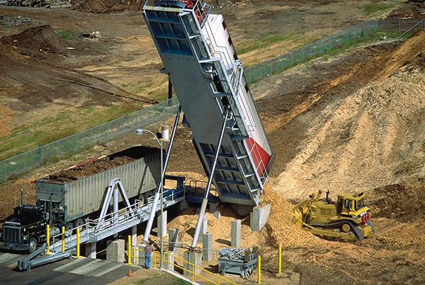
Although the CFB boiler was designed for coal, ENEL added a biomass fuel feed system. Figure 2 shows the Sulcis plant’s biomass handling, processing, and yard bin area. Wood chips are received by truck from local sources. The fuel is stockpiled outdoors and reclaimed by front-end loaders. Wood chips are screened and stored in the yard and boiler bins. A completely independent biomass handling and feed system was constructed. The biomass is fed to the boiler via two of the three cyclone sealpots at the back wall of the furnace. Biomass is a maximum of 15% of the fuel input by heating value.
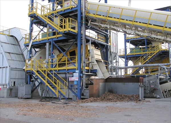 |
| 2. Biomass, Italian style. ENEL’s Sulcis Plant in Portoscuso, Sardinia, Italy was retrofitted with a circulating fluidized bed boiler and a biomass-handling system. (Units 1 and 2 have been removed.) A completely separate wood chip–handling system supplies up to 15% of the fuel input by heating value. Courtesy: Energy Associates |
In Europe, the world’s largest fluidized bed boiler is the 460-MW, once-through supercritical unit at the Lagisza Plant in Poland. (See “Operation of World’s First Supercritical CFB Steam Generator Begins in Poland,” Sept. 2009.) It began commercial operation in June 2009, replacing two of seven existing units. The CFB unit is designed to cofire up to 10% biomass by weight. The biomass-feeding equipment was considered in the design so that biomass could be added at a later date.
In the U.S., the $1.8 billion, 668-MW gross/585-MW net, Virginia City Hybrid Energy Center near St. Paul, Virginia, is currently being constructed for Dominion Virginia Power by the Shaw Group. This plant will have two Foster Wheeler CFB boilers that will utilize waste coal as their principal fuel plus up to 20% biomass.
This biomass-feeding system for Virginia City has four identical boiler feed systems supplying more than 175 metric tons per hour of wood chips and forest residuals to the two CFB boilers. Pre-sized biomass will be delivered by belt conveyors to the feed system, which will meter the biomass into the boilers. The system will provide approximately 20% biomass by heating value or 117 MW.
Construction of the Virginia City Hybrid Energy Center began on June 30, 2008. The plant is projected to begin commercial operation in summer 2012 (Figure 3).
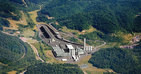 |
| 3. Dominion does biomass. This is an artist’s rendering of the Virginia City Hybrid Energy Center, which will use four identical boiler feed systems that will supply wood chips and forest residuals to two circulating fluidized bed boilers. Biomass will account for about 20% of the fuel input to the 558-MW net power plant when it is completed in summer 2012. Courtesy: Dominion |
Direct Firing in a CFB Boiler
Technology developments for the direct firing of biomass benefited from the Public Utility Regulatory Policies Act (PURPA), which was passed as part of the National Energy Act in 1978. It promoted the conservation of energy, efficient use of facilities and resources, and equitable rates for customers. It encouraged greater use of renewable energy by creating an expanded market by adding non-utility producers.
A variety of boiler designs were used under PURPA’s regulations, including bubbling fluidized bed, circulating fluidized bed, fixed grate stokers, sloping grate, traveling grate stokers, and water-cooled vibrating grates. These technologies typically are all available up to a 50-MW capacity for a single unit. Over that size, CFB becomes the technology of choice.
Like PC technology for coal, CFB technology scales up more easily for coal/biomass than stokers or grates. Major boiler manufacturers such as Foster Wheeler, Alstom Power, and Metso Power are offering 300-MW units for biomass and planning for the next-larger-size units. (See “FBC Control Strategies for Burning Biomass,” October 2010.)
Direct firing of biomass can also be added to a plant that has smaller, older, less-efficient coal-fired units by replacing one or more of those units with a modern, efficient boiler that is designed to best burn solid fuels, including biomass. Public Service of New Hampshire (PSNH), a subsidiary of Northeast Utilities, did just that at its Schiller Generating Station in Portsmouth, N.H. A new 50-MW combination biomass/coal-fired boiler replaced an existing, similarly sized unit. The project was undertaken to qualify for renewable energy certificates and to comply with lower emissions limitations.
The retrofit included a totally new biomass handling/storage/processing system and an extension from the existing coal-handling system to the new CFB boiler island. Figure 4 is a view of the boiler island during construction. In this view, the boiler’s cyclones are visible, before the building and systems were completed and enclosed. Schiller Station was awarded POWER’ s Marmaduke Award in 2007. A more complete description of the plant can be found in “PSNH’s Northern Wood Power Project Repowers Coal-Fired Plant with New Fluidized-Bed Combustor,” in our August 2007 issue.
 |
| 4. Work in progress. Public Service of New Hampshire retrofitted Unit 5 at its Schiller Station with a CFB burning 100% wood or 100% coal. This photo shows the boiler island during erection of the fluidized-bed combustor, before the building shell was completed. Courtesy: PSNH |
For new generation capacity, there are good reasons to consider a CFB boiler. This technology is proven and has been used since the 1980s. Numerous plants equipped with a CFB boiler utilize agricultural, forest, mill, and urban biomass products. When forethought is given to boiler and plant design, a variety of solid fuels can be used, as needed, due to availability, market, regulatory, or other circumstances.
Drax Power has been investigating the addition of three 300-MW biomass-fired CFB plants in the UK. One would be located adjacent to the existing 4,000-MW coal-fired plant and another would be sited in the Port of Immingham. Sites for the third plant are being evaluated. A variety of biomass fuels are being investigated including wood chips, wood pellets, miscanthus, straw pellets, bagasse, and logs. Initially, much of the fuel will be imported while indigenous sources are developed.
Fuel Issues for Large Boilers
At the outset of any project, the combustion engineer and boiler manufacturer will seek to establish a variety of parameters that define the design basis for the boiler. Site conditions such as air temperature, humidity, elevation, and cooling water temperature affect plant design. Knowing the type of fuel that will be supplied to the boiler is very important because fuel properties and characteristics affect boiler design and operation. Different solid fuel boilers have unique design and fuel requirements. For example, the fuel injected into a PC boiler is an inappropriate size for a stoker boiler. Particle size, the percentage of volatiles, total ash and moisture content, ash constituents, and heating value are all key parameters considered by the boiler engineer.
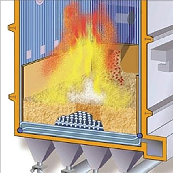
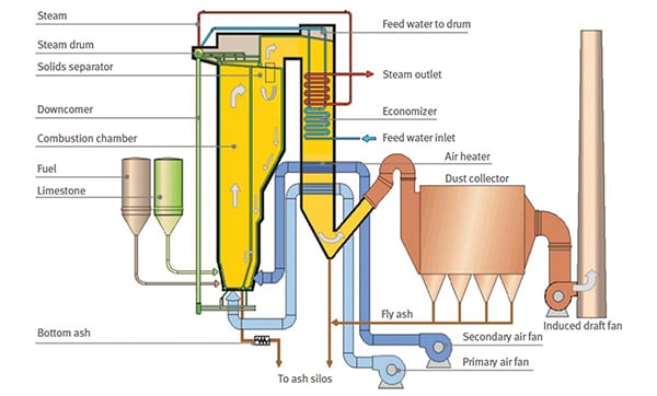
CFB boilers are different than other combustion technologies. The CFB boiler has relatively low combustion temperatures, has long combustion residence time, and the injection of limestone into the furnace allows the CFB boiler to use a wide range of fuels while controlling emissions using standard technologies.
In a CFB boiler, fuel is generally combusted in a bed of material (typically sand) that is expanded at a pressure/velocity that is above the particle’s saltation velocity, but below the particle’s transport velocity, to sustain fuel particles in the fluidized state. This enhanced turbulence allows a longer residence time to fully combust the fuel. The mass, volume, and shape of particles are important to the efficiency of this process.
The fuel feed to a CFB boiler will encompass a range of particle sizes, from sand-sized grains to small lumps. For any given fluidizing velocity, smaller particles will transport much easier than larger particles, but they will also fully combust more quickly. CFB boilers use cyclones to separate the smallest (fly ash) particles from larger particles that may be only partially combusted. Larger particles are discharged to the bottom of the cyclone’s sealpot/loop seal and are reintroduced/recycled to the combustion bed. The combustion gases and fly ash are discharged through the top of the cyclone to the superheater and economizer. The particle removal performance of the cyclones is dependent upon particle size and flue gas velocity.
Boiler manufacturers and standards organizations have developed particle size curves to identify fuel requirements for CFBs. Figure 5 illustrates the typical acceptable size range of biomass fed to a CFB, Austrian standard ÖNORM M 7133, “Chipped Wood for Energetic Purposes—Requirements and Test Specifications.” Particle mass, size, shape, and volatile content are key parameters considered in developing the acceptable fuel supply size curves. The fuel particle’s fluidizing and combustion characteristics establish the shape and characteristics of the curve.
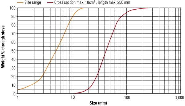 |
| 5. Sizing wood fuel. A CFB boiler requires properly sized fuel to operate efficiently. Few industry specifications for wood fuel exist; Austria’s ÖNORM M 7133 provides acceptable sizing for chipped wood used for boiler fuel. In this standard, acceptable particle sizes/quantities are those between the orange and red lines. The curve can be read that no more than 4% of the fuel supplied can be less than 1 mm. At 80%, the size distribution should have 80% of the particles between 5 mm and 63 mm; 95% of the particles should be no less than 100 mm. The cross-section maximum is 10 square centimeters, and maximum length is 250 mm. Source: ÖNORM M 7133 |
Some boiler manufacturers impose distinct fuel requirements to meet contract performance guarantees and warranties, depending upon the design fuel and contract terms. The cofiring of biomass fuel in a PC boiler imposes similar requirements, although the particles are larger, perhaps crushed by an air-swept hammermill to less than ¼ inch.
Controlling particle size to meet contract terms and boiler guarantees is important. Biomass-handling systems typically include screens and hogs to control particle size. However, fuel processing is typically not the responsibility of the boiler manufacturer. Nor does the boiler manufacturer typically supply the fuel or furnish the fuel preparation system. Managing this project interface often becomes a contentious issue among the fuel supplier; engineering, procurement, and construction contractor; boiler supplier; and owner during commissioning and the plant acceptance test.
Biomass Fuel Properties Must Be Accounted For
A large number of component materials are generically known as biomass. The choice of one over the others is usually determined by which option can provide the energy content (kJ) desired rather than by the weight of fuel purchased.
Some biomass fuels present unique utilization issues. Wheat straw, for instance, has very high levels of chlorine, and its ash chemistry is dominated by silica from the phytolith inorganic structures that have significant potassium. For other forms of biomass, fuel degradation and spontaneous combustion are important concerns. The amount of moisture in the fuel is a factor in the purchase, storage, and usage of all biomass fuels. Details of some of the more common biomass properties, and strategies for dealing with them, follow.
Temperature- and Moisture-Related Problems. Biomass is subject to two different natural processes, one a low-temperature process and the other a high-temperature process. The low-temperature process involves the growth and respiration of microorganisms, such as aerobic mold-fungi and bacteria. The high-temperature process is due to oxidation of the cellulosic materials. Biological heating, under the influence of water content or air humidity, can increase biomass temperatures high enough to trigger oxidation of the cellulose material, which can start a fire.
Wet biomass does not pose a spontaneous combustion problem because above a 60% moisture level, too much energy is needed to increase the water temperature to 100C and then evaporate it. This high energy demand drops the temperature of the biomass below the level needed to sustain combustion. Biomass will, however, continue to degrade due to biological activity.
At moisture levels between 20% and 60%, both degradation and spontaneous combustion become a concern. This range of moisture is what a plant will most often encounter. The large surface area of particles like wood chips—and their irregular shape, which traps small air pockets—provides a near-ideal environment for the breakdown of fibers. That, in turn, increases surface temperatures and the potential for spontaneous combustion. Smaller chip sizes increase the total surface area and the probability of biological heating.
Conversely, dry biomass can be stored for long periods. Dry biomass has too little moisture to support biological activity and, without biological heating or another ignition source, it is relatively stable.
Energy Density. For biomass products such as wood chips, one of the limitations to consider is its relatively low volumetric heating value or energy density. This is a property that is not normally of concern for other solid fuels. The lower mass heating value and low bulk density (kg/m3) combine to significantly reduce its volumetric heating value. As a result, many more railcars, much larger stockpiles, and wider belt conveyors are necessary to deliver and store the energy equivalent of other solid fuels.
Plants firing wood chips, for example, require six times the volume of bituminous coal on a kJ/m3 basis. The increased storage, processing, and handling system space required can become significant for large biomass-fired plants.
Fuel Blending as a Mitigation Strategy. Cofiring biomass, coal, and possibly other solid fuels enables plants to mitigate fuel-usage concerns. Blending multiple fuels into a designer fuel can help plants to best meet boiler/combustion, emission, and economic requirements.
Controlling fuel quality and cost by processing and blending biomass products on-site is a standard industry practice.
Not all biomass products are completely suitable, and the amount of some, like straw or miscanthus pellets, may be limited due to their chlorine and potassium content, which creates deposition/corrosion concerns. When different, less-suitable products are used, accurate control of the blending process is important for combustion.
Managing Variable Flow Characteristics. Flow characteristics are important to the design of any solid fuel–handling systems, but they are a particular concern for all biomass project stakeholders.
Wood chips, chopped straw, and other agricultural products have poor flow characteristics. During storage in stockpiles and bins, biomass will compress in volume, and particles can become entwined, matted, and gain strength as a mass, rather than behaving as unique individual particles. Instead of having a sloping angle of repose, the sides of a reclaim stockpile can be vertical, which helps to address this problem. Better yet, biomass storage bins are often designed with negative wall angles; that is, the bins have walls that diverge: The bins are wider at the bottom than they are at the top, which is very different from the hoppers typically used for storing coal or other solid bulk products. Chute angles and the choice of liner materials should be determined based on the biomass’s poor flow properties.
As noted above, due to availability, economic, combustion, and other reasons, different biomass products are often purchased and blended. The blended product can have much poorer flow properties than if any single product were used alone. The meshing of different particle sizes/shapes and the compressibility of the blend has a lot to do with this physical attribute.
Pretreating Biomass
For the most part, large biomass power plants cannot depend on a local industry to supply fuel, just as most coal-fired power plants cannot depend upon an adjacent mine. One reason for the distance from a fuel source is that siting generation facilities near power consumption centers is usually a key consideration. When biomass must be shipped long distances, pretreatment offers several advantages.
The down side of pretreatment options described below is that pretreatment increases fuel cost. For a small plant with a local source of biomass and unique conditions, there are good reasons to avoid pretreatment. But for larger plants that depend upon large, distant, multiple fuel sources, the savings in transportation, handling, and operation can easily offset fuel preparation costs.
A biomass pretreatment industry is developing to address some of the following issues:
- To help the wide variety of biomass products better match up with the narrow fuel specifications for most boilers.
- To lower the relatively high costs of transportation, handling, and storage.
- To reduce plant investment, maintenance, and labor costs by using a homogenous, consistent fuel for combustion.
Pelletization. One example of pretreated biomass is pellets. Biomass pellets are available from a growing number of sources. A variety of biomass feedstocks can be used for pellets, including bagasse, corn cobs and screenings, peanut shells, sawdust, switchgrass, and wheat middlings.
The pelletization process dries the feedstock, grinds oversized material, compacts and extrudes the fine particles, and then cools the product into a homogenous, high-energy-density fuel. Conditioners and binders are sometimes added. The pellets are cylindrical in shape and 6 mm to 8 mm in diameter and 15 mm to 25 mm in length. Pellets are a convenient biomass product for cofiring in a coal-fired plant.
Though pellets from different manufacturers may appear to be similar, their fuel properties are inherited from the source feedstock material, and quality is dependent upon the manufacturing process. Pellets manufactured from sawdust might be directly suitable as a fuel, but pellets manufactured from switchgrass might be limited to no more than 10% of the blended biomass fuel. Likewise, some manufacturers may use a binder such as starch, while other processes will depend upon the biomass’s cellulosic lignin, which with heat and moisture acts as a binder to form a dense pellet.
The amount of handling and exposure can also affect the quality of the delivered product. Receiving a shipment of wood pellets that has degraded into mostly sawdust can be very disconcerting when you are expecting a cargo of free-flowing, hard/clean, relatively dust-free pellets.
Like grain and other agricultural products, biomass pellets must be protected from the weather. They will swell when exposed to moist conditions and subsequently degrade to their original particle size and density. That is why pellets typically are stored in silos (as shown in Figure 1), a dome, an A-frame building, or other configuration. Covered storage for pellet stockpiles is needed at large biomass power plants and is one of the primary factors that increases the plant’s biomass fuel–handling system cost.
Torrefaction. Another form of biomass is briquettes. Biomass briquettes are larger than pellets, typically 30 to 100 mm in diameter, and can be a composite product formed from a blend of biomass and coal.
To form briquettes, a process of torrefaction is used. Torrefaction is a thermochemical process that alters the properties of biomass, improving its physical properties for handling and utilization. Torrefaction heats biomass to between 200C and 300C, typically for an hour, in a reducing environment. Volatiles are consumed, and the biomass is converted to a char product with increased energy density and improved grindability, uniformity, and durability.
The torrefaction process minimizes some of the quality control issues that might otherwise be encountered because:
- Different types of feedstocks can be used.
- The decomposition reactions of torrefaction loosen the fibrous structure of biomass, which improves the grindability of biomass, reducing the energy needed to size biomass particles.
- Fungi growth and biological activity are inhibited.
The next pretreatment step is processing the torrefied biomass into pellets, which further improves the biomass physical properties.
Torrefaction and pelletization are complementary processes. Torrefaction first increases product durability and reduces biological degradation, while pelletization increases its energy density.
Torrefied pellets can be stored in outdoor stockpiles and handled much like coal. They have perhaps half of the energy density of coal, which is a big improvement in comparison to untreated biomass products. The ability to handle and store torrefied biomass much like coal can significantly reduce the capital cost for converting an existing coal-fired plant into a cofiring one.
Integro Earthfuels in the U.S. and Topell, BV in the Netherlands are two companies that are moving from the pilot stage to their first commercial biomass torrefaction/pelletizing plants.
Learning from Experience Is Important
The DOE’s National Renewable Energy Laboratory (NREL) examined the experience of 20 biomass plants in a study conducted in 2000. The lab identified several key issues that affected these plants: fuel cost, location, fuel handling, reliability/dependability, partnerships, and subsidies. Both the good and bad experiences are of value to those hoping to develop successful cofiring projects. Here are several lessons learned.
Fuel cost was the highest priority at most plants. Because there is normally a direct correlation between fuel cost and fuel quality, fuel quality trade-offs played an important role in plant design and operation.
The location of a biomass power plant affects it in a couple of ways. First, there can be local circumstances that become permit and community requirements. These can increase operating cost due to the need to curb traffic, restrict operations that are noise/odor sources, and pay high tax/labor rates. Second, the distance to biomass resources is important because the typically low energy value of biomass in comparison to coal, oil, and gas can quickly raise fuel cost as the transport distance increases. For example, Rio Bravo Rocklin Power Station was selected as a Top Plant (December 2009) for improved wood fuel purchasing, handling, and combustion system modifications that were made to reduce plant operating costs.
Most plants in the NREL survey experienced a significant learning curve. They spent a lot of time and money the first couple of years solving problems such as fuel stockpile heating/odors, excessive equipment wear, handling hang-ups and bottlenecks, tramp metal problems, and wide fluctuations in fuel moisture content. They also learned about meeting environmental standards while operating with variable conditions and without excessively corroding heat transfer surfaces or slagging boilers beyond the point of prudent operation.
Many biomass plants significantly changed fuels over the years. This is not unusual for the utility industry. Many PC boilers, which were originally designed to use bituminous coal, switched to low-sulfur Powder River Basin coal. They once may have been fitted with scrubbers but have now switched to a high-sulfur Illinois coal. The operational differences introduced by firing biomass can be significant, so designing for fuel flexibility is a good strategy. The Colmac Plant in Mecca, Calif., for example, found it economical to modify its permit to allow the use of petroleum coke (see “Colmac Energy Inc.’s Biomass-Fueled Power Plant,” December 2010). At times, waste fossil fuels can be more economical than biomass products, and the properties of one can offset those of another.
Plants with the best long-term operating records placed a high priority on plant reliability and dependability. This must be stressed during both plant design and operation. Staying on top of maintenance programs and maintaining a clean/neat workplace are essential for long-term reliability.
For those plants with close ties to a limited number of customers and fuel suppliers, the relationship or partnership with those firms is important. For instance, a saw mill may be a primary fuel supplier and be a consumer of the biomass-generated power; in this example, the mill and power plant have a mutual interest in each other’s success. In instances where the interests of the partners diverge, both parties suffer.
Many biomass or cofiring plants were constructed with the aid of PURPA’s regulations or under circumstances where the legislature obligates customers to pay higher rates for electricity generated by other available technologies. Subsidy programs, however, do not last, and competition will affect the long-term financial future of the plant.
Biomass Is a Prime-Time Fuel
The power industry is facing conflicting goals that make a sustainable, dependable fuel like biomass an option worth considering. Cofiring biomass is a way for large, existing solid fuel power plants to diversify their fuel base. Because biomass can be a secondary fuel, utilities can test the technology and build a network of suppliers in a relatively low-cost and low-risk program.
For a variety of reasons, no one energy conversion technology best meets all operating conditions. Biomass is a fuel that can deliver on many counts now, and new pretreatment technologies are at hand to make it a fuel that is more familiar, convenient, and economical for large power plants. For utilities that are planning new power plants, biomass is a strategic fuel to add to the list of options.
Consumers of all sizes rely on affordable, dependable electricity, and biomass plants can meet baseload, cycling, and peak demands. Reducing emission levels and conserving our finite resources are key components for achieving a sustainable environment, and biomass is one way to help achieve these goals.
— Daniel Mahr, PE (danmahr@energy-pc.com) is the president of Energy Associates PC and an expert in the handling, blending, and processing of coal, biomass, and other bulk commodities. He is a past chair of ASME’s Fuels & Combustion Technology Division and was a contributor to ASME’s Material Handling Handbook.