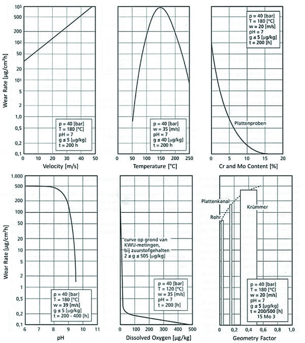
Oxygen levels in just parts per billion dissolved in the feedwater stream for boilers and heat-recovery steam generators (HRSGs) can cause pitting and reduce the operating life of steam cycle components. That’s why reliable steam plant operation relies on low dissolved oxygen levels in boiler and HRSG feedwater systems to limit pitting and related corrosion damage to carbon steel components, including deaerator vessels and storage tanks, piping, and boiler tubes.
Traditionally, many power plants have relied on a deaerator vessel and storage tank to liberate dissolved oxygen in feedwater by raising its temperature by direct injection of saturated steam. Usually, the steam is provided by an extraction line or by dedicated supplies from a low-pressure source such as the low-pressure (LP) drum in a combined-cycle plant.
The deaerator removes oxygen just prior to feedwater entering the boiler economizer section of the HRSG, making conditions near the optimum (approximately 300F) for flow accelerated corrosion (FAC) damage to carbon steel components. Components with a change in flow direction–such as upper tube bends, piping elbows, and high-fluid-velocity regions in deaerator vessels–are especially vulnerable. Also, because operating pressures in deaerators are typically slightly above atmospheric, the vessel shell and head thicknesses required by ASME Code are relatively thin compared with those of higher-pressure vessels such as steam drums. If protective magnetite layers are damaged, a rapid wall thinning can occur in areas that are exposed to high local velocities under adverse water chemistry.
These corrosion mechanisms are well known to the industry, so it is incumbent on plant management to assess the rates of degradation and take actions to correct water chemistry deficiencies that will accelerate FAC, among other failure mechanisms, and to project conservative estimates of remaining equipment life.
The following case study details a recent incident in which FAC damage rapidly degraded the high-pressure (HP) deaerator vessel shell and how management responded to effectively maintain reliability and protect personnel safety.
Isolated plant
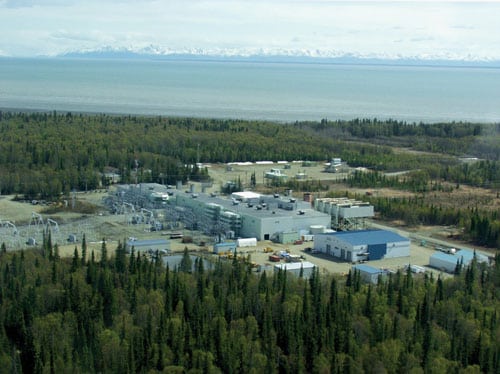
The Beluga Power Plant (Figure 1) operates in perhaps the most difficult conditions encountered by a combined-cycle power plant in North America: It is located about 40 miles due west of Anchorage and is accessible only by barge or airplane. POWER profiled the plant’s technical details (March 2006) in a report describing Beluga’s first 25 years of operation and specific measures taken to ensure reliable operation. The plant is owned and operated by Chugach Electric Association (CEA), which is headquartered in Anchorage and is the largest electric utility in Alaska.
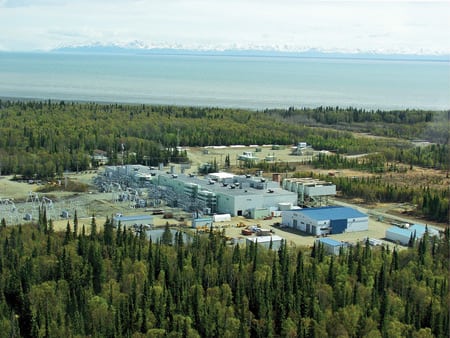
1. Wilderness outpost. The 210-MW, 2 x 1 combined-cycle Beluga Power Plant, located 40 miles west of Anchorage, supplies power to the surrounding area. Courtesy: Chugach Electric Association Inc.
More than half of CEA’s thermal generation is produced by its gas turbine fleet operating in simple-cycle operation; the remainder is generated by Beluga Power Plant’s two ABB-11DM gas turbines, which operate in a 2 x 1 combined-cycle configuration with vintage Babcock & Wilcox HRSGs supplying the single-pressure BBC steam turbine. HRSG bypass stacks allow simple-cycle operation with either HRSG out of service. Total power produced by the plant is approximately 210 MW.
Determining deaerator integrity
The original Burns & Roe plant design provided two dedicated deaerator systems: one for the HP steam system (providing deaeration for both HRSG HP economizers) and the second for both LP steam systems. Each deaerator system provides boiler feed pump suction for three 50% boiler feed pumps.
The steam turbine is single-pressure; LP steam is used today only for the deaerator steam supply. Vessels and tanks were provided by L.A. Water, a fabricator owned at the time by Chromalloy Corp.
Originally, the plant was designed with a “soft water” system, which was not unusual for the relatively low HP steam system operating pressure (about 650 psig). In the mid-1990s, this system was replaced with a demineralized water system to address recurrent problems with high silica levels in the steam drums.
The upgraded water treatment system reduced the water’s silica content but yielded water conditions that at times can be highly aggressive, particularly in high-turbulence and high-flow components such as the feedwater pumps and deaerators. Periodic water chemistry transients have also increased the frequency of aggressive water conditions that can further accelerate corrosion damage to these components.
Periodic inspections of the deaerators were performed by the plant maintenance department, a local nondestructive examination firm, and the plant’s ASME Code mechanical contractor. Both deaerator systems had a history of recurring damage that required numerous repairs (Tables 1 and 2). As the steam plant approached its end of design life (25 years), the frequency and severity of damage increased, and related damage was occurring in both boiler feed pump systems.
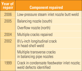
Table 1. Excerpts of the ASME Code repairs made to the HP deaerator vessel. Source: Chugach Electric Association Inc.
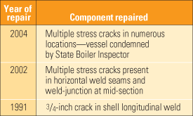
Table 2. Excerpts of the ASME Code repairs to the LP deaerator vessel. Source: Chugach Electric Association Inc.
Tube leaks in the air-cooled condenser have also occurred periodically, but routine cleaning and temporary repairs have maintained the reliability of this critical component.
Oxygen levels as high as 100 ppb were occasionally recorded in the mid-1990s. Management responded by instituting annual helium leak testing and routine vacuum decay testing on the steam turbine as well as periodic isolation of pumps to identify sources of air in-leakage. As the plant ages, these activities become critical to maintaining sufficiently low air in-leakage to allow the deaerator systems to perform as designed.
The LP deaerator was abandoned in 2004 after extensive pitting and stress cracking had damaged the vessel shell to the point where efforts to make repairs were unsuccessful. At that time, a modification was made to the plant feedwater piping to modify the remaining HP deaerator to supply suction feedwater to both the LP and HP feedwater pumps. This modification was reasonably simple: Two tees were installed to provide a connecting branch between the HP and LP pump suction lines. Calculations by plant engineering staff confirmed that adequate head existed to prevent pump cavitation and that the original (overcapacity) storage tank was large enough to provide a sufficient source of suction flow.
Rigorous inspections
Starting in 2005, detailed inspections of the HP deaerator vessel and storage tank were performed, compliant with the standard practice specified by NACE in RP0590-96 (the latest version is now NACE SP0590-2007) “Standard Practice for Prevention, Detection, and Correction of Deaerator Cracking.” These included visual inspections, pit depth surveys, ultrasonic testing of remaining shell wall thickness, and wet fluorescent magnetic particle testing of pressure vessel welds. An inspection opening was cut in the tray shroud (baffle) to provide access to the LP steam piping nozzle and weld connection. Additional cracks and preexisting damage were repaired in both 2005 and 2006.
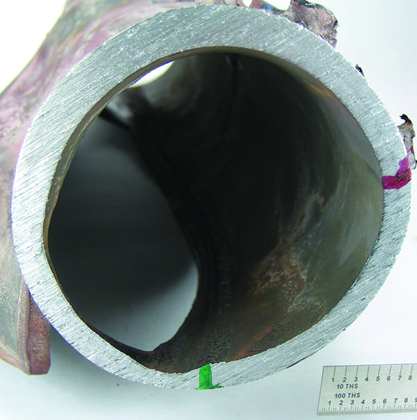
During a scheduled outage in April 2007, a relatively large area on one end of the HP deaerator vessel closest to the LP steam nozzle was identified as having noticeable wall loss since prior inspections (Figure 2). The damage mechanism was identified as flow accelerated corrosion, which is common in deaerator systems and is caused by high local velocities and temperatures that maximize the corrosion rate.
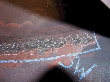
2. Engraved invitation. This photo of FAC wear damage to the HP deaerator vessel shell was taken in April 2007. Courtesy: Chugach Electric Association Inc.
FAC damage has also been confirmed as the primary mechanism responsible for recurring damage to HP boiler feed pump impellers (Figure 3) and for wall thinning of HP economizer tubes in the HRSG, whose progression has been trended for several years.
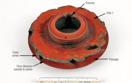
3. Total loss. FAC wear damaged each of the plant’s three HP boiler feed pump impellers. Courtesy: Chugach Electric Association Inc.
Plant management decided to schedule several interim inspections of the HP deaerator to better characterize the FAC damage and its rate of progression. The first special inspection was in August 2007; a second was in December 2007. These special inspections confirmed a relatively rapid rate of progression and a need to plan for component replacement (Figure 4).
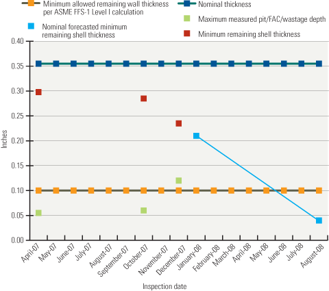
4. Death sentence. This was the HP deaerator vessel remaining life projection made in December 2007. Source: Chugach Electric Association Inc.
As an interim measure, a deflector plate was installed to attempt to reduce the flow rate near the most degraded part of the vessel shell. Subsequent inspections indicated that this measure was in part responsible for reducing the rate of local shell wall thinning.
Fitness for continued service and estimates of remaining lifetime were demonstrated by the procedures prescribed in Parts 5 and 6 of ASME FFS-1 (formerly referred to as API Standard 579 “Fitness-for-Service”) for pitting damage and local wall thinning. The procedure for local wall thinning was validated by the Welding Research Council, as documented in its Bulletin No. 505 released in 2005. These standards and procedures provide a “more sophisticated assessment of metallurgical conditions and analyses of local stresses and strains can more precisely indicate whether operating equipment is fit for its intended service or whether particular fabrication defects or in-service deterioration threaten its integrity. Such analyses offer a sound basis for decisions to continue to run as is or to alter, repair, monitor, retire, or replace the equipment.”
Calculations performed using these fitness-for-service standards indicated that the HP deaerator vessel was fit for continued service until August 2008, provided that the rate of continued thinning did not exceed an amount assumed in the assessment. Three successive inspections confirmed that this was indeed the case. By late March 2008, FAC damage had consumed about one-third of the initial wall thickness, clearly representing a significant degradation since the initial detection in April 2007 (Figure 5).
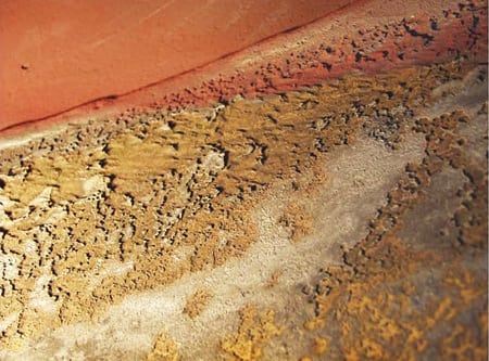
5. Surface of the moon. This March 2008 photo shows FAC wear damage to the HP deaerator vessel shell in the same location as Figure 2. Courtesy: Chugach Electric Association Inc.
Short-term plan needed
The Beluga steam plant is needed until at least 2014, and possibly beyond, to meet regional load requirements. The HP deaerator system is critical to proper operation of the steam plant and to preventing pitting and related damage from affecting all carbon steel components–including piping, certain valves, and most of the HRSG boiler. Based on the apparent rate of degradation identified by late 2007, it was clear that the remaining HP deaerator vessel was degrading at a rate that precluded a high probability of long-term reliable operation.
As a result, corporate management decided in late 2007 to proceed with procurement and replacement of the existing HP deaerator and the previously abandoned LP deaerator to restore the plant to its original configuration. The project schedule for procurement, fabrication, and delivery of the new vessels was very aggressive. Fabrication shop backlog and delivery uncertainties added to the project’s challenges.
A purchase specification was prepared by Chugach with the joint support of Black & Veatch and Tetra Engineering. Then an order was placed by Chugach in early 2008 with Kansas City Deaerator for fabrication and delivery of the new vessels and storage tanks to the Port of Anchorage. Corporate purchasing and engineering worked closely with the supplier to ensure an on-schedule delivery.
Delivery scheduling is critical for the Beluga plant, as large component deliveries are possible only via barge due to the plant’s remote location. By land, the plant is accessible only by a local gravel road that has no access to the south central Alaska road system around Anchorage. The barge landing, rebuilt every spring to repair winter damage, can only be accessed during periodic high-high tides that provide sufficient draft for a barge to land.
The new vessels and tanks were delivered slightly ahead of schedule in late June (Figure 6). Removal of the old vessel and storage tank commenced in early July, as planned, using the plant’s crane and a specially constructed temporary steel structure (Figure 7). Installation is expected to be complete later in the summer. Hydrotesting, performance verification, and insulation work should be complete before cold weather arrives in October (Figure 8).
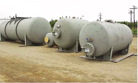
6. New tank upgrade. New deaerator vessels and storage tanks in the construction staging area, ready for installation. Courtesy: Kansas City Deaerator

7. Tanks for the lift. In July 2008 the HP deaerator storage tank was ready for installation. Courtesy: Chugach Electric Association Inc.
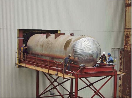
8. Tight squeeze. A temporary structure was erected for removal and installation of the replacement vessels. Courtesy: Chugach Electric Association Inc.
Future preventive measures
A comprehensive review of the plant water chemistry program and monitoring system capabilities and related operating procedures was conducted in late 2007 to address deficiencies and to implement operational improvements. Many recommendations were provided to align plant operations and instrumentation with industry practice, with emerging recommendations from the ASME committee with oversight on HRSG water chemistry guidelines, and with the recently issued (2006) ASME Consensus Operating Practices for Sampling & Monitoring of Feedwater/Boiler Water Chemistry for Modern Industrial Boilers (ISBN 0791802485).
Since then, plant management has obtained additional outside support for its water chemistry program and procured needed instrumentation. Corporate management has committed to a series of improvements and plant upgrades to water chemistry to reduce future risks of corrosion and degradation.
In addition, inspections of such elements as piping wall thickness (Figure 9) were recently performed to assess the extent of FAC damage on other components in the feedwater, condensate, and LP steam system–all of which connect to the deaerator system. Areas with significant wall thinning will be trended by future inspections, evaluated for fitness for service by the ASME FFS-1 procedure, or replaced, as necessary, to maintain a highly reliable steam plant.
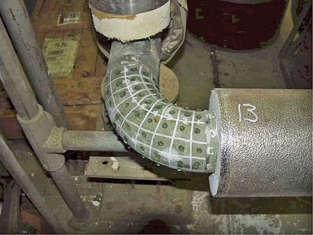
9. Detailed examination. Inspection of the HP economizer inlet piping elbow found FAC damage. Courtesy: Chugach Electric Association Inc.
—Peter S. Jackson, PE (pjackson@tetra-eng.com) is director of field services for Tetra Engineering Group Inc. Trey Acteson (trey_acteson@chugachelectric.com) is the plant manager of the Beluga River Power Plant, Chugach Electric Association.