It is fairly common for power plant engineers and maintenance managers to focus on fireside issues rather than waterside issues during routine maintenance outages. However, that could be a mistake. Waterside problems in boilers and heat recovery steam generators (HRSGs) can result in catastrophic failure and widespread damage, significantly affecting plant reliability and availability.
Oftentimes, power plant resources and inspections are focused on detecting and fixing boiler and heat recovery steam generator (HRSG) fireside issues. Fireside problems are relatively easier to identify and address. However, waterside problems are often not recognized until catastrophic failure occurs or until the problems are too widespread to be easily remedied. This can result in severe damage to valuable assets, which significantly diminishes plant reliability and availability.
Waterside issues create a greater nuisance because they are not only a reliability factor but also a significant safety concern. For instance, flow-accelerated corrosion (FAC) is a huge issue in HRSGs because of higher fluid velocities along with multi-pressure systems. FAC damage can lead to under-deposit corrosion (UDC) problems in high-pressure (HP) evaporator sections. Also, corrosion fatigue is a major concern in utility boilers and HRSGs. These failures typically occur in the work space and may lead to human injuries or even loss of life.
Condenser leaks, feedwater upsets, and/or inappropriate feedwater chemistry can lead to severe UDC issues such as hydrogen damage, caustic gouging, and acid phosphate corrosion. Hydrogen damage is like a cancer to boiler tubes; if detected in one location, it is more than likely present in other areas of high heat flux, flow disruptions, and lazy flow circuits. Severe deposit accumulation in HP circuits or high-heat flux areas causes a variety of boiler and HRSG challenges.
The majority of waterside issues are related to feedwater chemistry, contamination, layup procedures, load cycling, and ramp rates. The individual failure mechanisms appear to be so simple to understand, but things get complicated when several variables come into play. Root cause determination is complicated with poor data collection (chemistry logs) for long-service units along with unknown/unidentified condenser leaks, chemistry upsets, and other factors.
HRSGs
A typical combined cycle plant joins two thermodynamic cycles such as high-temperature Brayton gas cycle to a moderate- to low-pressure (LP) Rankine cycle. A HRSG is typically part of the Rankine cycle or the production of process steam where it utilizes the waste heat from a gas turbine to generate steam with or without auxiliary duct burners. There are far fewer pollution issues in combined cycle units. Sulfur oxide and particulate matter emissions are minimal when burning natural gas in a combined cycle. Nitrogen oxide (NOx) emissions can be managed using the addition of selective catalytic reduction, selective non-catalytic reduction, low-NOx burners, or flue gas recirculation.
The number of stages in a HRSG can be from one to four (the thermal efficiency increases by increasing the number of stages). The HP and intermediate pressure (IP) stages can be used for power production. The IP stage can also be used for steam extraction to inject steam in the gas turbine for NOx control and attemperation in the steam cycle. The LP stage is used for feedwater heating and deaeration.
The systems in the HRSG operate with demineralized makeup water along with high-quality condensate for feedwater. Many drum units operate with more than one pressure stage. The water treatment is challenging in multi-pressure systems. Also, the optimum chemistry can be different for each stage. Steam/water should be pure enough to mitigate corrosion and fouling issues in the gas turbine because they typically use coolant (steam) from the HRSG IP stage to reduce NOx emissions, increase thermal efficiencies, and offset material constraints in the gas turbine.
Chemistry and Water Treatment Schemes
Coordination of material selection and water treatment practices play an important role in waterside issues in boilers. The purity of feedwater and steam is one of the most important criteria for efficient and reliable operation of a power plant. Proper pretreatment and chemistry control greatly reduce the formation of deposits and boiler tube failures.
Boiler feedwater refers to a combination of returned condensate and makeup water. The first-ever full-scale central power station (Pearl Street Station) was developed by Thomas Edison in September 1882 using steam engines. However, water treatment technology did not start until the late 1800s and early 1900s, and has experienced significant changes since then. Prior to that time, formation of hard scale and severe corrosion led to boiler tube failures and explosions.
Soda ash/washing soda (Na2CO3) was the first chemical used to treat boiler water. Sodium phosphate (conventional phosphate treatment) surpassed soda ash in the late 1920s. Caustic treatment using sodium hydroxide (NaOH) was very popular until the 1960s. However, developments in the power industry (higher pressures and temperatures) caused a significant concern for caustic gouging and caustic embrittlement. Therefore, refinement to conventional phosphate treatment occurred.
The use of phosphate chemicals in boilers is about 100 years old. Phosphate provides good buffering of acids and hydroxides, and precipitates residual hardness in removable sludge form. Several phosphate-based treatments evolved such as coordinated/congruent (CPT) and equilibrium phosphate treatments (EPT). Previously, the majority of the drum units in the U.S. used CPT, and studies indicated that many suffered phosphate hideout and acid corrosion issues. Acid phosphate corrosion occurs with the use of mono- or di-sodium phosphates, but not with tri-sodium phosphates.
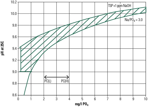
Conventional phosphate-based programs are used in boilers operating below 1,000 psig. Coordinated phosphate program uses di- and tri-sodium phosphates to minimize free hydroxide issues. It follows a sodium to phosphate ratio of 3:1. Congruent phosphate uses a sodium-to-phosphate ratio of 2.6:1 with increased phosphate level. Cycling units and boilers with substantial waterside deposits must operate with reduced phosphate levels to avoid excessive hideout. Therefore, EPT was developed with lower levels of phosphate along with up to 1 ppm of free OH. This program can be used in boilers operating above 2,500 psig, but below supercritical pressures.
Phosphate hideout in HP boilers can be prevented by switching to EPT. Caustic treatment is typically used in LP boilers. Chelant-based treatment is used in boilers operating below 1,000 psig. Excess chelant can attack clean boiler surfaces. Polymer treatment is effective in LP boilers of less than 1,200 psig; thermal stability is a limiting factor in polymer treatment. Drum boilers typically use a mixture of di- and tri-sodium phosphate, and morpholine or ammonium hydroxide (amine) for pH control. Amines, apart from ammonium hydroxide, are not suitable for high-temperature applications as they decompose at elevated steam temperatures.
Permissible limits of contaminants in the feedwater are reduced with higher pressures. Increasing the pressures into the supercritical region and the development of once-through boilers demanded the requirement of no-solid-addition chemical treatments. Therefore, all-volatile treatment (AVT) and oxygenated treatments (OT) were developed. AVT chemistry varies under reducing conditions—AVT(R)—and under oxidizing conditions—AVT(O). AVT and OT treatments are typically used in conjunction with condensate polishers. However, condensate polishers are not mandatory for subcritical and drum-type boilers.
Although NaOH and Na3PO4 are not allowed in AVT, these chemicals can be used during startup conditions and as a response during emergency contamination periods. Feedwater solids should be less than 0.05 ppm in once-through boilers and supercritical boilers. AVT(R), AVT(O), or OT are used in these high-pressure boilers. Feedwater pH should be maintained from 9.3 to 9.5. Typical chemicals are ammonia and hydrazine, which can only be used in units containing copper-based feedwater heaters (FWHs); the total hardness should be about zero.
Carryover and Layup Issues
Carryover from a steam drum causes significant issues downstream such as corrosion of high-temperature superheater/reheater circuits. Also, erosion, fouling, and stress-corrosion cracking issues in HP and LP turbines can occur.
Carryover can occur in two ways, mechanical (leaving small droplets of water with steam due to poor separation equipment and high drum levels) and vapor carryover. Silica is volatile and may cause a concern for volatile carryover. Alkalinity increases carryover in the presence of suspended matter. Vapor carryover is very difficult to control; the best method is to reduce unwanted solids in the feedwater.
Many boilers spend a significant time in layup, awaiting further use. If oxygen is not removed from the waterside, the tubes can suffer localized pitting and corrosion, especially underneath deposits. The majority of oxygen-pitting corrosion can occur during layup periods.
The presence of salts can accelerate corrosion of boiler steel. Corrosion activity is significantly higher during the first few minutes to hours following the shutdown when a moist and aerated environment exists along with higher metal temperatures. Unit cycling and rapid shutdown/startup for short-term outages are more detrimental than longer, planned outages with controlled shutdowns.
A short-term layup involves periods extending overnight or through a weekend. A typical layup procedure is wet layup for hot/warm startups. Short-term layup assumes that the unit will be required to operate within a relatively short notice. An intermediate layup consists of periods extending more than a weekend and up to a few weeks. This duration could be for relatively short planned outages. Either wet or dry methods can be implemented. A long-term layup involves periods extending from a few weeks to several months. This duration could include major equipment repairs, planned outages, or a long-term layup due to system load requirements, which could include mothballing. Both wet and dry approaches can be applied. The decision can be taken based on the availability of infrastructure to maintain wet or dry conditions.
Prior to the shutdown, the blowdown rate should gradually be increased via continuous and bottom blowdown. Chemical feed rate may need to be increased to offset the additional chemical loss through the higher blowdown rate. The solids level must be reduced to prevent potential precipitation. As water cools while shutting down the boiler, solubility of most solids decreases, and they precipitate. It is important to fill with deaerated, demineralized water to prevent corrosion, deposit accumulation, and waterside stress-assisted corrosion (corrosion fatigue) during startup periods. The risk for corrosion fatigue is much higher during this time because the transient stresses are higher and chemistry is difficult to control.
Boiler and HRSG Waterside Issues
Water reacts with steel to form iron oxide on the inside diameter (ID) surface of the waterwall and economizer tubes. Iron oxide that formed elsewhere in the boiler, intentionally added feedwater chemicals, and feedwater corrosion products can deposit at the tube ID surface. These deposits settle where gravity and flow disruptions (such as the root pass of tube butt welds) are present. Also, high-heat flux zones (about 10 feet above the burner elevation) are susceptible to the formation of thick deposits.
In HRSGs, these deposits accumulate on the hot side of HP evaporator and generating bank tubes. In water-touched tubes, usually the thin inner layer is dense due to reaction of steel (passive layer) and water; the thicker outer layer is porous due to deposition of solid particles. UDC is often seen in roof tubes, the top of the nose arch, and at the burner elevation where significant deposits can accumulate.
As deposits develop, the tube temperature increases, as the thermal conductivity of the deposit is much less than that of the steel tube. The net result is higher metal temperatures, and even thicker deposits and more rapid corrosion underneath. Deposits form at the ID surface by settling suspended particulate solids, usually iron oxide and feedwater chemicals collect by boiling within the porous deposit. A localized acidic or basic corrosion environment can form underneath the thick deposits, leading to significant wall wastage.
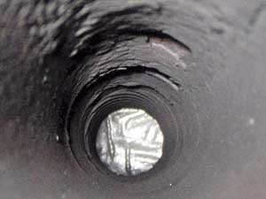
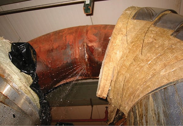
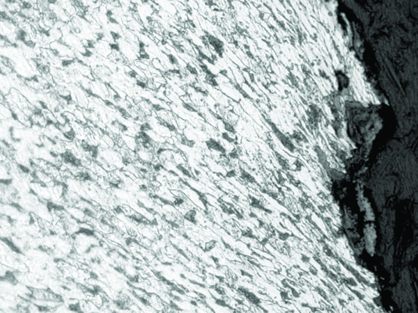
Thick and tenacious deposits can also promote hydrogen damage in boilers operating at greater than 1,200 psi (Figure 1). Hydrogen damage rarely occurs with little or no wall thinning, but in most cases, damage develops with significant wall wastage. Under acidic conditions, the hydrogen ion reacts with steel to form a positively charged iron ion and atomic hydrogen. Hydrogen damage is more prevalent in acidic environments, but it can also occur in strongly basic environments.
 |
|
1. This image shows the inside of a roof tube that experienced thick-edge failure. It is from a 45-year-old Babcock and Wilcox boiler that operated with a drum pressure of 2,400 psi. The tube material is SA-210 A1 steel, and it had thick deposits on the inside diameter (ID). Courtesy: David N. French Metallurgists |
Acid phosphate corrosion is the second mode of waterside UDC. Phosphate corrosion occurs where thick deposits are present with the right combination of feedwater chemicals and localized flow disruption or a localized concentrating mechanism.
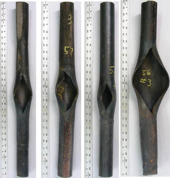
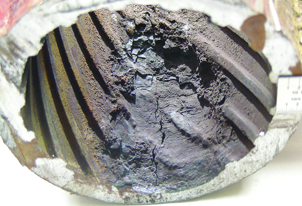
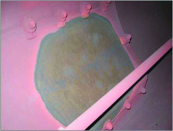
The third form of UDC is caustic attack. Caustic concentrates within the deposit by evaporation of water leaving behind the hydroxide. The other caustic attack is a gouged surface in the absence of thick deposits; this second mode typically results from feedwater upsets and/or departure from nucleate boiling (DNB). Load cycling and low-load conditions can promote caustic gouging (Figure 2).
 |
|
2. This image shows a cyclone roof tube that experienced thin-wall overload failure. It is from a 20-year-old boiler that was load cycling. The tube material is SA-178C steel. No ID deposits were found, but its ID surface had caustic gouging. Courtesy: David N. French Metallurgists |
Susceptibility to FAC and subsequent UDC is much higher in HRSG units than in conventional plants. Therefore, no oxygen scavenging chemicals are used in HRSGs (mechanical scavengers are allowed). Also, these units should be designed with all-ferrous metallurgy rather than mixed metallurgy. Mixed metallurgy can be used in FWHs that operate with relatively lower pH of 8.8 to 9.2; however, all-ferrous metallurgy in FWHs can be operated at a slightly higher pH of 9.2 to 9.5. Iron oxide dissolution will be reduced with higher pH. Therefore, single-phase FAC issues can be mitigated with higher pH conditions. Copper-based materials may still be present in condensers.
Under-Deposit Corrosion
Deposits form at the ID surface by settling suspended particulate solids (usually iron oxide) and feedwater chemicals within the porous deposit. A localized acidic or basic corrosion environment can form underneath the thick deposits, leading to significant wall wastage. Dissolved excess oxygen also promotes the wastage rate. Additionally, during shutdowns, water can stay in the horizontal tubes or low spots and be exposed to oxygen from the air, resulting in oxygenated corrosion. Therefore, oxygenated corrosion can occur when online or offline.
Significant tube wastage occurs underneath the thick deposits due to UDC. The thick deposits that cause overheating of the tube result in bulges and creep degradation. Thick deposits along with the right corrosion environment may also promote hydrogen damage, acid phosphate corrosion, and caustic attack at the ID surface. Feedwater contamination (condenser leaks), chemistry upsets, ingress of untreated water into the steam cycle, and inadequate/inappropriate chemistry control strategies are the prime reasons for deposit accumulation and UDC.
Hydrogen Damage. Hydrogen damage is the principle mode of waterside UDC. Hydrogen damage rarely occurs with little or no wall thinning, but in most cases, damage develops with significant wall wastage. Hydrogen damage is more prevalent in acidic environments, but it can also occur in strongly basic environments.
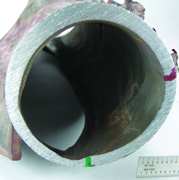
Under basic conditions, the hydroxide ions react with iron to form iron ferroate ions and atomic hydrogen. The atomic hydrogen is trapped underneath the deposits and diffuses into the steel along the ferrite grain boundaries. Iron carbide in the steel reacts with diffused hydrogen to form a large molecule of methane. This large methane molecule cannot diffuse through the grain boundaries, so it collects there and develops significant pressure, leading to grain boundary cracks (Figure 3), and eventually a thick-edge, low-ductility failure. Depending on the extent of damage, a complete decarburization may also occur in the microstructure. The end result is a microstructure that contains intergranular cracks and is decarburized.
 |
|
3. This image shows decarburization on the fracture face, intergranular cracking, and grain boundary fissures in SA-210 A1 carbon steel tube material under 250x magnification. Courtesy: David N. French Metallurgists |
Acid Phosphate Corrosion. Acid phosphate corrosion is the second mode of waterside UDC. Phosphate corrosion occurs where thick deposits are present with the right combination of feedwater chemicals and localized flow disruption or a localized concentrating mechanism. Excessive addition of mono- or di-sodium phosphates in the water treatment chemicals leads to phosphate corrosion.
The corrosion product will be white or grey maricite (NaFePO4). The addition of tri-sodium phosphates does not cause acid phosphate corrosion. This corrosion is localized where the phosphate hideout occurs. The failures are typical overload failures with no significant microstructural degradation. Nowadays, acid phosphate corrosion failures are rare due to improved chemistry practices.
Caustic Attack. The third form of UDC is caustic attack. Caustic concentrates within deposits by evaporation of water leaving behind the hydroxide. The wastage occurs between the thick deposit and the steel.
A second form is caustic gouging. Under the right flow and pH conditions, caustic may concentrate at the edges of steam bubbles formed. An upset of the boiler chemistry with too much sodium hydroxide (NaOH) or localized concentration of hydroxide increases the tube wastage dramatically. In this case, no deposit exists and the resultant morphology is one of a smooth, rippled, clean ID surface.
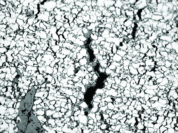
Caustic removes the protective iron oxide and bare steel reacts with NaOH to form sodium ferroate (NaFeO2) or sodium ferroite (Na2FeO2). The affected surface appears to be smooth and undulating. Typical failures are overload ruptures with no significant microstructural degradation (Figure 4). A DNB condition may exist, resulting in a stable film or steam blanketing. Corrosive species (hydroxides) concentrate at the edges of the blanket/bubbles, causing severe metal loss. The majority of times, chemistry upsets with too much hydroxides play a major role in caustic gouging. Close chemistry control strategies along with rifled tubing can eliminate caustic gouging.
 |
|
4. This image shows overload rupture, ferrite and pearlite, in SA-178 C carbon steel tube material under 250x magnification. Courtesy: David N. French Metallurgists |
Flow-Accelerated Corrosion
FAC is still one of the leading failure mechanisms in HRSGs and conventional boilers, although it has been recognized for more than 50 years. In earlier days, single-phase FAC was very familiar. However, two-phase FAC was not clearly understood until two decades ago.
FAC is particularly higher in HRSGs due to higher fluid velocities resulting from a significant increase in volume from liquid to steam as it passes through the LP evaporator tubes. Also, multi-pressure systems and changes in fluid volume have a significant effect on FAC in HRSG units. FAC could be a precursor of UDC as iron transportation to high-heat flux areas from the feedwater train. Feedwater contamination is another major source of deposits to settle in the high-heat flux areas and lazy circuits.
FAC is nothing but the dissolution of protective magnetite in the presence of the right environment; this dissolved magnetite is transported when turbulent flow exists. This process repeats in a cycle so that wastage occurs at a faster rate. FAC can occur in single-phase (water only) and two-phase (water and steam mixture). The higher dryness fraction in the fluid reduces the susceptibility to two-phase FAC and completely eliminates FAC in saturated steam.
Operating temperature plays an important role in FAC because it affects the formation and dissolution of oxide. At higher temperatures, the formation of iron oxide is controlled by the temperature. At moderate temperatures, the magnetite layer is porous and irregular, making it vulnerable to FAC. However, the formation of iron oxide is limited at low temperature and it purely depends on the chemistry within the system.
Single-phase FAC is typically associated with boiler feed pumps and nearby components such as the deaerator and feedwater piping. Single-phase FAC is consistent with orange peel surface appearance and chevron marks. Two-phase FAC damage is typically found in pressure differentials between the source and recipient components. Horse-shoe pits, enamel-like appearance, tiger striping, and a clear color difference of red and black are characteristics of two-phase FAC.
Single-phase FAC occurs between 100F and 400F with peak damage occurring at about 280F. On the other hand, two-phase FAC occurs at a slightly higher temperature range of 250F to 500F with peak damage at about 300F. Single-phase FAC is significantly affected by the reducing environment (<10 ppb oxygen). Solubility of magnetite reduces with the oxidizing environment. Therefore, it is recommended to operate units with OT or AVT(O) without adding oxygen scavenging chemicals specifically in once-through boilers, supercritical units, and HRSGs. However, this chemistry conflicts with mixed metallurgy (copper-based equipment) in the feedwater system because copper tolerates operation under a reducing environment.
Although OT (30–150 ppb oxygen) is recommended, air in-leakage is strongly discouraged for several reasons. In some drum units, the chemistry does not coincide with the color appearance because of air in-leakage. Oxygen scavenging chemicals are consumed by more air in-leakage and feedwater components change to red color (hematite [Fe2O3] and iron oxide hydrate [FeOOH] rather than magnetite [Fe3O4]). This might be beneficial for carbon steel components; however, it plays a detrimental effect on copper-based equipment and copper transportation.
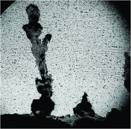
The oxidizing-reducing potential does not have any effect on two-phase FAC because the oxidizing potential is associated with the steam phase and the surfaces touched with the liquid phase are still susceptible to FAC. Therefore, promoting an oxidizing environment has no beneficial effect on two-phase FAC. This phenomenon can be easily distinguished with the color appearance (Figure 5). Black, darker appearance is from a reducing environment and red-colored appearance is from an oxidizing environment.
 |
|
5. This image shows two-phase flow-accelerated corrosion in a low-pressure drum. Courtesy: David N. French Metallurgists |
Material selection plays an important role in single-phase as well as two-phase FAC. Research indicates that carbon steel materials are susceptible to FAC. Adding chromium to the steel reduces the solubility of oxides due to the presence of stable chromium oxides. In complicated situations where options for controlling FAC are limited, material upgrade could be the only option to mitigate FAC—the higher the chromium content, the lower the susceptibility to FAC (single- or two-phase). Therefore, material upgrade to at least 1-1/4 Cr steel is recommended in chronic FAC cases.
Another important aspect of FAC is turbulence. The laminar flow in smooth tubing/piping does not cause FAC. It needs a turbulent flow (reducers, bends, deaerator shells, valves, and the like) for mass transportation of dissolved oxides. Magnetite dissolution will be significantly affected by the pH of the feedwater; it is the second-most-important factor for FAC. Magnetite dissolution is less with higher pH. However, there is a limitation on pH in drum boilers containing mixed metallurgy in the feedwater train because copper tends to corrode at elevated pH. HRSG units may need to be controlled with different pH for individual pressure stages (if possible) to mitigate FAC issues.
A plant’s water treatment scheme should be included in the design stage of a power plant/HRSG. Therefore, material selection, specifically in the feedwater train, should depend on the water treatment program. Nevertheless, if the water treatment scheme is selected based on the plant’s metallurgy, then the plant may need to be operated with potential FAC issues. Ensure the water treatment program is changed following a material upgrade in the feedwater heat exchange equipment. If this upgrade is not done in a timely fashion severe wastage can occur in carbon steel materials. Carbon steel prefers an oxidizing environment while copper-based materials favor reducing environments with relatively lower pH.
Corrosion Fatigue
Corrosion fatigue, sometimes called stress-enhanced or stress-assisted corrosion, describes the waterside condition that leads to catastrophic failures due to localized cracking in regions of high stress. These failures typically occur in the work space. The problem occurs in water-wetted tubes in both waterwalls and economizers at attachments, such as buck-stay attachments, on the colder side of the tube. On occasion, the damage is a series of concentric rings of cracks that outline the attachment weld on the outside.
The failures predominantly occur on the cold side of the tube. However, corrosion fatigue can still exist on the hot side of the tube or along the membrane. In economizers, strain can occur at the tube bends, welds, and heat-affected zones. The corrosion component during corrosion fatigue consists of the following:
- ■ Low pH
- ■ Excessive oxygenated water
- ■ Contaminants in the form of chlorides and sulfides
Startup conditions consist of a hot waterwall and a relatively cool support structure. The cooler buckstay attachments prevent thermal expansion of the tubes, which leads to a compression along the membranes. In the wind box, the preheater combustion air may expand the support steel faster than the waterwalls and stretch the tubes parallel to the membranes. Regardless of the temperature differentials, an applied strain is generated within the furnace.
A cross section through a corrosion-fatigue crack shows a wide, irregular, bulbous form, or shape to the crack surfaces; the crack tip is often blunt or rounded (Figure 6). The non-uniformity to the sides of the crack suggests several episodes of corrosion occurring even after the crack was well established. Such cracks may be widened during a chemical cleaning. A rash of leaks may be found after cleaning, as the removal of oxide or corrosion debris has removed the “plug.” Cracks of this morphology are more common in cycling units.
 |
|
6. This image shows corrosion fatigue cracks in SA-178 A carbon steel tube material under 63x magnification. Courtesy: David N. French Metallurgists |
Guidelines to Prevent Waterside Issues
Waterside issues can be minimized with proper metallurgy selection, a suitable water treatment program, periodic sampling, and chemical cleaning, along with proper maintenance, operation, and layup procedures. The following guidelines will help in mitigating or reducing waterside issues:
- ■ Clean boiler tubes periodically. A clean boiler can eliminate potential UDC and phosphate hideout issues.
- ■ Avoid the combination of oxygen and moisture when the unit is idle (short-term or long-term). Carefully dry the unit with the igniters before opening it to the atmosphere.
- ■ Conduct periodic tube sampling from representative areas. This can identify serious waterside issues before they become catastrophic.
- ■ Use rifled tubing in the high-heat flux areas to reduce caustic gouging and UDC.
- ■ Avoid feedwater chemistry upsets, coolant flow reductions in tubes, excessive overfiring/blowdowns, and load swings, which all contribute to caustic gouging. Partial flow restrictions can also promote caustic gouging.
- ■ Prevent the source of contamination in the case of thick deposits. Shutdown the unit immediately in the case of contamination ingress.
- ■ Reduce flow disruptions in tubes. For example, avoid using backing rings during butt welding.
- ■ Select a unit-specific feedwater treatment program. Equilibrium phosphate control can be adopted for drum units operating at 2,500 psi, but avoid the use of mono- or di-sodium phosphate.
- ■ Control caustic levels in feedwater chemistry.
- ■ Keep the amount of particulate iron oxide as low as possible through blowdown to prevent build-up of thick scales. However, be aware that heavy blowdowns may offset feedwater chemistry, which can lead to other issues.
- ■ Monitor high-heat flux zones along with high-stressed areas for UDC and corrosion fatigue, respectively.
- ■ Perform non-destructive examination to identify UDC and hydrogen damage, specifically on the HP evaporator tubes, slope tubes, roof tubes, and high-heat flux zones. All hydrogen-damaged tubes should be replaced; chemical cleaning cannot remove these extremely thick and tenacious deposits.
- ■ Shutdown the plant and perform chemical cleaning if a major contamination event occurs. Prolonged operation during this time can adversely affect the pressure parts.
- ■ Avoid pad welding on hydrogen-damaged and corrosion-fatigued tubes, and also on thin-wall tubes (less than 0.125”), because of the possibility of burn-through, which causes flow disruption. Also, copper from waterside deposits can diffuse into tubes if not removed prior to welding, resulting in embrittlement.
- ■ Select a water treatment scheme consistent with FWH tube metallurgy and change the feedwater chemistry following FWH metallurgy upgrades. Systems with all-ferrous metallurgy (although condensers may contain copper-based materials) should be operated with either OT or AVT(O) with an optimum pH range of 9.2 to 9.6. Air in-leakage should be prevented. Units with mixed metallurgy, that is, FWHs containing copper-based materials, require a reducing environment to prevent copper corrosion. They should be operated at a pH range of 9.0 to 9.3. However, be aware that interconnecting carbon steel components may be susceptible to FAC.
- ■ Analyze proposed system modifications thoroughly before proceeding. Changing geometry to mitigate FAC may not provide fruitful results without a thorough case study. The damage pattern may be shifted to a different location or exacerbated. Upgrading from carbon steel to low-alloy steels containing higher chromium in areas susceptible to FAC provides satisfactory results.
- ■ Control single-phase FAC with oxidizing potential. Two-phase FAC cannot be reduced with oxidizing potential, however, as oxidizing power is associated with the gas phase. Options are limited to control two-phase FAC. The majority of the time material upgrade to low-alloy steel could be the only option to reduce two-phase FAC.
- ■ Change chemistry from reducing to oxidizing potential after upgrading FWH metallurgy from copper to stainless steel, otherwise, serious FAC damage can occur in carbon steel components.
- ■ Maintain proper pH levels. Low pH conditions play an important role in pitting corrosion, corrosion fatigue, UDC, and single- and two-phase FAC.
- ■ Keep iron level in the feedwater less than 2 ppb for all-ferrous metallurgy—note that systems with OT produce iron concentration less than 1 ppb. In mixed metallurgy systems, copper level should be less than 2 ppb.
- ■ Implement a comprehensive FAC program to manage FAC damage. Inspections along with non-destructive techniques should be used to assess FAC damage.
- ■ Control FAC in LP circuits by adding chemicals (NaOH or phosphates) to the LP drum, but only when the LP drum does not provide feed to the IP/HP circuits or attemperator.
- ■ Operate multi-pressure HRSG systems in an oxidizing environment, such as AVT(O) or OT, without addition of oxygen scavenging chemicals. HRSGs should be designed with all-ferrous metallurgy or an upgrade should be in order to prevent FAC and UDC issues.
- ■ Monitor iron concentration in the feedwater and LP drum. Results will provide an indication of whether FAC is active or not. Total iron concentration should be less than 2 ppb in the feedwater and less than 5 ppb in the drum to eliminate the possibility of active FAC.
- ■ Inspect tubes via non-destructive examination, such as linear phased array or radiography, for corrosion fatigue cracking in the areas susceptible to corrosion fatigue, and replace tubes damaged by corrosion fatigue. Follow Electric Power Research Institute guidelines to locate areas susceptible to corrosion fatigue. Pad welding should be avoided on corrosion fatigue-damaged tubes because it exacerbates corrosion fatigue due to higher residual stresses.
■ Reduce ramp rates because transient stresses, along with feedwater chemistry, play a significant role in developing corrosion fatigue. Corrosion fatigue occurs with the synergistic effect of stress large enough to fracture the magnetite (Fe3O4) scale and feedwater with high oxygen concentration or low pH.
Tools for Success
The successful operation of a conventional power plant or HRSG primarily depends on water/steam side chemistry. A combination of several strategies needs to be implemented to minimize boiler/HRSG tube failures and increase a plant’s reliability and availability.
First, impurities need to be minimized to the required target levels from makeup water/condensate. This can be achieved with the use of condensate polishers, purification of makeup water, blowdowns, and deaeration. In the second method, selecting and maintaining the right feedwater chemistry to control pH and oxygen control. Third, evaluating and managing chemistry control strategies in extended periods of operation outside specified limits, emergency protocols for ingress issues, load swings, startup/shutdown, and layup procedures. The majority of internal damage to the pressure parts can occur from offset conditions rather than normal operation.
Plant personnel training should be in a continuous order to maintain high-quality feedwater to the pressure parts. It is not possible to prevent every waterside failure mode in a real-world environment. However, understanding and locating susceptible locations along with suitable plant chemistry knowledge can make life easier. Furthermore, scheduled maintenance can be managed more effectively by allocating the right resources to the right place.
Understanding where and why failures occur, along with connecting unknown dots, give intense knowledge about a plant. Eventually, major and catastrophic failures, along with epidemic damage to the internal surfaces, can be prevented. ■
—Rama S. Koripelli, PhD, PE (rkoripelli@davidnfrench.com) is the technical director for David N. French Metallurgists.