The Hague’s century-old power plant, now owned by E.ON, provides electricity to the local grid and thermal energy for the city’s district heating system. Poor performance from the plant’s 25-year-old equipment and The Hague’s wish to become a carbon-neutral city by 2010 gave birth to the idea of repowering the existing plant. For protecting a historic building while investing in low-emissions electricity generation, achieving improved plant efficiency and reliability, and accelerating the project so the plant could be back online for the next heating season, The Hague Repowering Project is the winner of POWER’s 2009 Marmaduke Award for excellence in O&M. The award is named for Marmaduke Surfaceblow, the fictional marine engineer and plant troubleshooter par excellence.
Den Haag (The Hague), Netherlands, known as the "International City of Peace and Justice," hosts about 150 international legal organizations, including the International Court of Justice, the primary judicial arm of the United Nations. The world’s first peace conference, which convened in The Hague in 1899, eventually led to establishment of the Permanent Court of Arbitration, the world’s first court for settling international disputes, and the predecessor of the International Court of Justice.
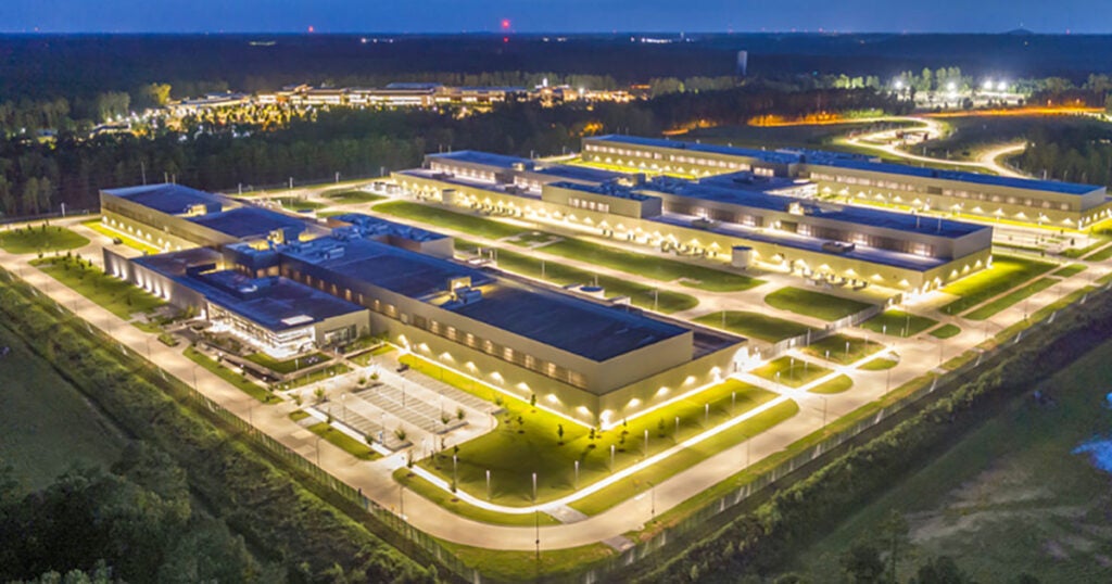
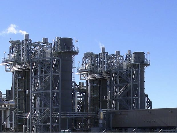
Much of the grand architecture in the historic areas of The Hague dates from the latter half of the 19th century and the early 20th century, when the city was modernized and prosperous. The grandeur of The Hague continued to grow with each passing year until the destruction brought on by the deportation of its citizens, occupation, and later liberation of the city caused by World War II. Today, Monumentenzorg (The Bureau for Monuments and Historical Sites) requires owners of historic buildings constructed prior to 1945 to preserve their façades and the buildings’ other cultural-historical qualities. The Hague’s original power plant, located in the center of the city, is one such building. The exterior looks the same today as when the plant first entered commercial service in 1906 (Figure 1). Since 1978 it has also provided district heating to many homes, businesses, and government offices, including the World Court.
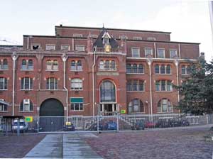
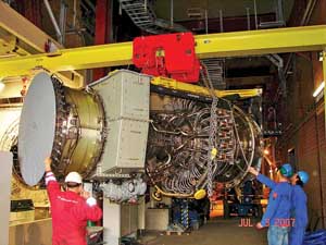
1. In the prime of life. The Hague Repowering Project removed two old gas turbines and generators and replaced them with state-of-the-art aeroderivative gas turbines to improve the plant’s efficiency and power output—all within the confines of the plant’s historic 1906 building near the city center. Courtesy: E.ON
Heat and Power Provider
The Hague’s Electriciteitsfabriek or Electricity Factory, located on De Constant Rebecque Square in the city center, is owned by E.ON Benelux and is one of the oldest still-operating combined heat and power (CHP) plants in the Netherlands. The building that houses this plant remains attractive. However, its beauty is more than skin deep.
The generating plant originally consisted of five steam engines and multiple boilers and generators. A number of changes were made over the years. In 1983, Unit 15 — consisting of two combustion turbines, two heat-recovery steam generators (HRSGs), and a single condensing steam turbine with extraction steam — was added. It was the only unit operating prior to the latest repowering. The nameplate capacity of this plant was 75 MW electric with 80 MW thermal, although actual production over the past decade was much lower.
The extraction steam is used to produce hot water that is circulated through the district heating system to large buildings such as those housing the government building department and the Dutch parliamentary complex. By 2005, operating inefficiencies and the expiration of its heat supply contract meant the time had arrived for the power station to enter the digital age.
At the end of 2006, E.ON, as purchaser and distributor of heat to The Hague; ENECO Energie, a leading Dutch energy company with the contract to distribute the heat to customers; and the city of The Hague reached an agreement that ensured the supply of district heat to the city through 2023. The new agreement also supports the municipal leadership’s goal of making The Hague a climate-neutral city by 2010. According to Joost van Dijk, chairman of the Board of E.ON Benelux, "We were able to take on this responsibility to society because the city council has given district heating an important place in its policy around CO2. This is an excellent example of shared, lateral thinking whereby all parties work together to enable this sort of massive investment." E.ON Benelux invested some €70 million ($97.9 million in mid-June) to complete the repowering project.
With a new district heat agreement in hand in November 2006, The Hague Repowering Project was soon under way. Energy Services Inc. (ESI) of Farmington, Conn., a subsidiary of United Technologies Corp., was selected as the turnkey contractor for the project based on its successful commissioning of a similar repowering project in late 2005 in Leiden, only 10 miles from The Hague. In the Leiden Repowering Project, two older combustion turbines were replaced with new-technology General Electric (GE) LM-2500+ turbines; the two existing generators and other process equipment were in serviceable condition and were reused. The Leiden Repowering Project, also located in a historic building, was successfully completed within a very tight three-month schedule, and E.ON predicted a three-year payback on its investment.
One of the first major challenges encountered by The Hague’s project team was timing the construction phase. Electricity supplies can be replaced by market purchases, but district heat supplies are another matter. "Although an investment of €70 million in the recently liberalised energy market entails major risk, stopping heat deliveries just wasn’t an option," said van Dijk. Much of the construction work to follow was scheduled to ensure that there would be no disruption to the district heating system during the next heating season, beginning in October 2007 (Table 1).
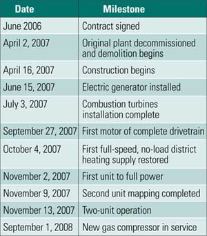
Table 1. Compressed project schedule. The repowering project had to be executed between winter heating seasons to ensure heat deliveries to The Hague’s district heating grid. The timeline for the gas turbine replacements was the project’s critical path. Source: ESI
Another major challenge was the very tight budget for the renovation. In fact, early feasibility studies in 2004 and 2005 were not optimistic that the project was economically feasible. Other options were investigated until a clear technical option that could be constructed within the project’s financial constraints was identified: replace the aging and unreliable combustion turbines with high-efficiency turbines, but reuse the existing HRSGs, steam turbine, and district heating equipment because these components were in good, serviceable condition.
One of the pivotal moments in this decision-making process was when the HRSGs were found to be capable of handling up to 25% more exhaust mass flow. The higher exhaust mass flow limit allowed ESI to specify larger and more efficient combustion turbines than was originally thought possible. Turbine specs were limited only by the space and volume available in the building and the existing location of the HRSG inlet flanges.
Major contractors and suppliers to the project are listed in Table 2.
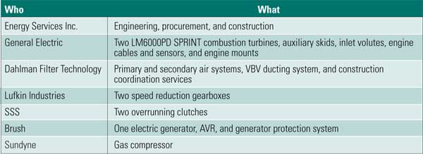
Table 2. Major suppliers to The Hague Repowering Project. Source: ESI
Combustion Turbine Specs
ESI made a close examination of the space and volume limitations of the power house and the arrangement of the existing HRSGs and concluded that a unique single-drivetrain arrangement — where a single, double-ended generator is powered by two combustion turbines — was the best technical selection for the project that provided adequate space to maintain the new equipment. There wasn’t a lot of room; in fact, the entire drivetrain would have to be shoehorned into an area only 100 feet long. GE LM6000PD SPRINT gas turbines were selected because of the engine’s compact size and high thermal efficiency. Gearboxes are required because the LM6000 operates at 3,600 rpm and the 50-Hertz generator runs at 3,000 rpm.
There were other advantages to this unique equipment arrangement. With just a single generator, the project was able to save the cost of a second high-voltage generator grid connection. E.ON’s redundancy specifications for this project were also met with the two, independently operated gas turbines. Furthermore, this arrangement gave E.ON additional and unexpected operating flexibility in managing its electrical grid’s spinning reserve and voltage support in this area of the country.
Operation of the two combustion turbines — one a cold-end-drive configuration (GT-1) and the other a hot-end-drive configuration (GT-2) — was managed by using an SSS clutch that connects each turbine-gearbox system to the generator. The different configurations of the LM6000 were required to match the rotational direction of the generator — the turbines are designed to rotate in a single direction and can’t be reversed except by selection of which end of the turbine attaches to the power output shaft. The drivetrain arrangement is well illustrated by an elevation view of the equipment shown in Figure 2. Unfortunately, because the project was so compact and placed inside sound enclosures inside the historic power house, no single photo can illustrate the equipment arrangement.
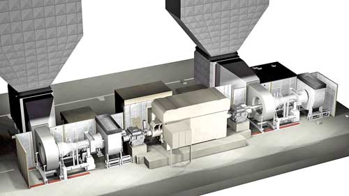
2. Close quarters. Two gas turbines are connected through gearboxes fitted with overrunning clutches to a double-ended generator to form the 100-foot-long drivetrain. Note that the GT-1 on the left is a cold-end drive LM6000PD combustion turbine, whereas the GT-2 on the right is a hot-end drive configuration. The different model turbines were required to match the rotational direction of the generator shaft. Note that the building penetrations were already in place and were only expanded to match the combustion air and ventilation needs of the new turbines. Equipment enclosures and ductwork are removed for clarity. Courtesy: ESI
The overrunning clutch allows a single turbine to operate when the second turbine is out of service. The second turbine can then ramp up its speed until the clutch locks into place when the turbine reaches synchronous speed. The second turbine can continue to ramp up load on the drivetrain until the rated power output of the entire plant is achieved. Shutting down a single turbine uses the same process, but in reverse — the SSS clutch is also able to disengage the turbine from the drivetrain during the no-load shutdown sequence. This arrangement provides the ultimate in operating flexibility for E.ON to meet any anticipated combination of power and district heating energy requirements (Figure 3).
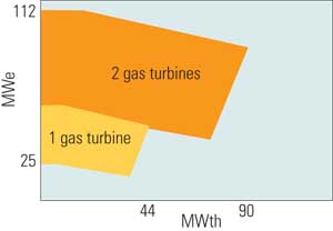
3. Flexible operation. Each combustion turbine can operate independently or simultaneously, depending on the city’s power and heat production needs. Source: ESI
The SPRINT moniker on the LM6000PD combustion turbine describes a unique capability with these dry, low-emissions engines: internal spray intercooling (hence, the name SPRay INTercooling). The LM6000 is a dual-rotor, direct-drive gas turbine derived from the CF6-80C2, high-bypass, turbofan aircraft engine. This engine is unique in that its power output is controlled by the compressor discharge temperature instead of the turbine inlet temperature, as in most other turbines. A portion of the compressor discharge air is used to cool a number of the high-pressure turbine components. Spraying water atomized by an eighth-stage air bleed into the airstream entering the five-stage low-pressure compressor and into the 14-stage high-pressure compressor inlet plenum cools the air as it is compressed, thereby reducing the compression power required.
The arrangement of the two gas turbines, generator, and SPRINT water supplies is illustrated in a control panel monitor screen capture shown in Figure 4. The performance data show the two combustion turbines to be operating close to full load but with SPRINT not engaged.
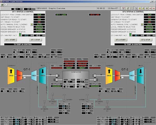
4. Always under control. ESI was also responsible for integrating the instrumentation and controls of both combustion turbines, gearboxes, auxiliaries, and the double-ended generator. Shown are typical operating data taken as a screen capture from the control panel monitor. Note the water connections for the SPRINT power augmentation system. Courtesy: ESI
With a lower air temperature leaving the high-pressure compressor discharge, additional fuel can be added that will increase the combustion turbine’s power and thermal efficiency. The positive effects of spray cooling are best appreciated during high ambient temperatures, when combustion turbines are notorious for their loss of power and efficiency. The SPRINT actually produces 4% more power and has a higher efficiency at ambient temperatures above 90F; that’s over 30% more power than the standard engine. Full SPRINT-rated load can be reached within 10 minutes of activating the system (Table 3).
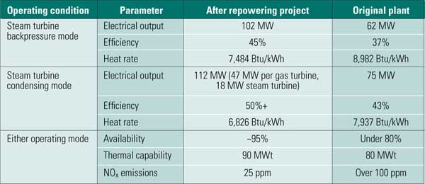
Table 3. The Hague Repowering Project performance parameters. All performance data are with the SPRINT system in service. Source: ESI
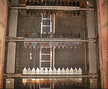
As luck would have it, the centerlines of the combustion turbine exhaust flanges of the two gas turbines were nicely aligned with the inlets of the two existing HRSGs, effectively eliminating what could have become a ductwork nightmare. The increased mass flow coming from the two new turbines did produce a slightly higher exhaust backpressure than that produced by the old plant, but that was expected, and it exacted only a small performance penalty. The only HRSG modification required was a new, smaller economizer that eliminated any potential for economizer steaming.
Preserving a Historic Building
No changes to the façade of the building were required with this equipment configuration, with one exception: The air inlet requirements must still be met by ductwork that penetrates the building façade, and those penetrations were enlarged to accommodate the increased airflow requirements of the new combustion turbines and the addition of anti-icing coils. These modifications were imperceptible to passersby when viewing the historic power plant’s exterior. The combustion and ventilation air intakes were placed inside the existing boiler house.
The only system that was not installed inside the power house was a new gas compressor, which was installed in a separate building, to move the hazardous operation out of the historic building. Other systems installed inside the power house included a new plant digital control system and a new water supply connection to supply water for the SPRINT feature on the two LM6000PD engines. An upgraded electrical interconnect to the ENECO grid to handle the increased power production also was installed. The existing 13,000 m3 (3.4 million gallon) heated water storage tank stores an abundance of hot water, so the gas turbines will normally be operated at their best efficiency mode. (See http://tinyurl.com/m3k9gr or the link in the www.powermag.com video archive for an animation of the project sequence.)
A Reconstructed Plant
Restoring the district heating system was the critical milestone that determined the entire project schedule, and the project’s critical path went directly through the delivery date of the two combustion turbines. After the project was given a full release, the contractor immediately began the demolition phase, working many weeks with two crews, six days a week and 16 hours a day to stay on schedule. See the sidebar for a series of photos that document the construction sequence.
The only long-lead equipment that wasn’t available for initial plant start-up was the fuel gas compressor. The very high pressure ratio of this aeroderivative gas turbine (30.7) is a key to its excellent thermal efficiency, but it also requires a very high natural gas supply pressure. For the LM6000PD, a new gas compressor was required to raise the fuel gas pressure from the typical 38 bar (565 psig) to 47 bar (695 psig) to reach the combustion turbine’s peak load. Until the new gas compressor was installed the combustion turbines were limited to about 90% of full load.
ESI reports few start-up problems with the combustion turbines; only a single gas fuel-staging valve has been replaced. The plant did experience some generator/gearbox train vibration, but the vibration abated after replacing one connecting shaft in May 2008. In June last year, one combustion turbine received some contaminated natural gas and had to be cleaned. Later that month, an insufficient oil supply to one of the SSS clutches in the gearbox forced a three-week outage to modify the oil supply system and repair premature wear of the clutch. That’s not a very long punch list of corrections for a project as detailed and complicated as this one.
For squeezing two gas turbines, two gearboxes, a double-ended generator, and all equipment supports and air management ductwork into a very compact space while significantly upgrading plant efficiency and performance — and doing so in a very short time without materially changing a historic building’s façade — The Hague Repowering Project wins this year’s Marmaduke Award. Congratulations to E.ON, ESI, GE, ENECO Energie, and The Hague for connecting the old with the new.
—Dr. Robert Peltier, PE is POWER‘s editor-in-chief.
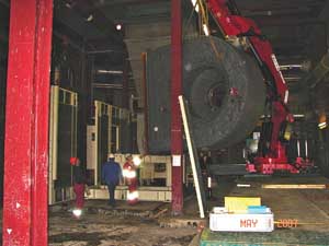
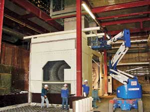
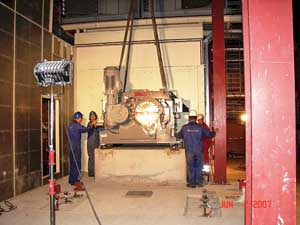
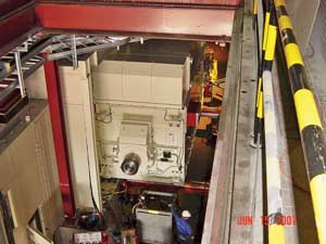
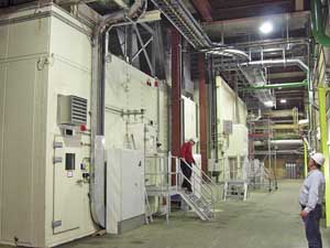
Construction Sequence for The Hague Power Station Repowering ProjectPerhaps the most challenging aspect of the project was squeezing two gas turbines, gearbox/clutch assemblies, and a double-ended generator into externally ventilated sound-attenuating enclosures in a very confined space. If a picture is worth a thousand words, then this photo sequence efficiently communicates the success of ESI’s well-planned erection sequence. The fuel gas compressor was a very long-lead purchase item with a delivery date months past the critical district heating season. The gas turbines were able to operate at reduced load until the gas compressor was commissioned the following summer. |