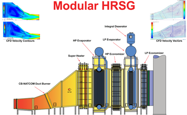
Duct burners use supplementary firing to increase the heat energy of a gas turbine’s exhaust, making it possible to increase the output of a downstream heat-recovery steam generator (HRSG). Early systems of the 1960s took a conventional approach to burner design. The exhaust of the turbine was directed into a windbox and then into a burner throat, where fuel was added and mixed with oxygen by high-pressure drops and swirlers. Simpler, grid-style systems were later designed to reduce the pressure drop and spread the heat out across the duct. The grid design uses an array of fuel manifolds to deliver the fuel into the turbine’s exhaust stream and a diffuser/bluff body attachment to stabilize the flame (Figures 1 and 2).
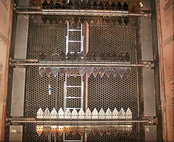
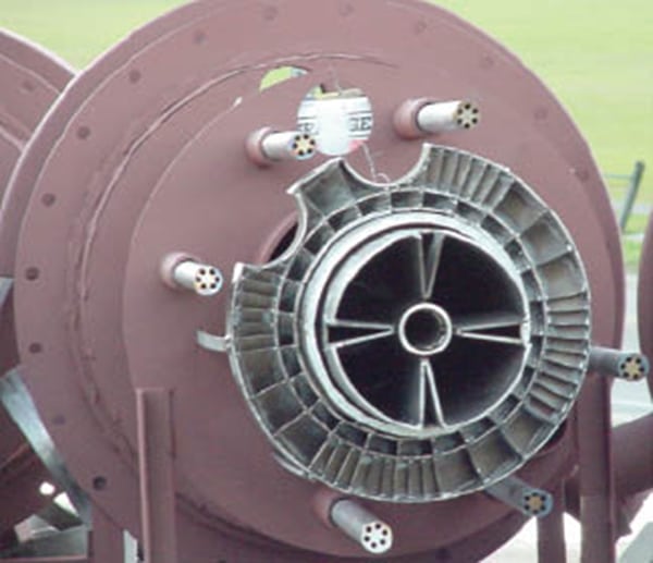
1. Spanning the width. In this photo of a duct burner being installed, fuel enters from the left through stainless steel piping and exits through a series of drilled orifices. Flame stabilizers of investment-cast stainless steel with “teeth” are designs used to improve combustion efficiency. A perforated plate distribution grid can be seen in the background. Courtesy: Forney Corp.
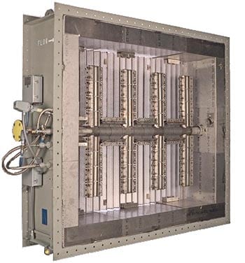
2. Integrated package. A prefabricated duct burner system for plants rated at 15 MW or less. The branched element design directs fuel through vertical and horizontal sections and includes an integral distribution grid. Courtesy: Forney Corp.
As gas turbine (GT) technology advanced, mass flow rates and exit temperatures rose along with combustion efficiency and nameplate ratings. In response to the increases, the cross-sectional area of HRSGs grew to increase the tube surface area available for heat recovery and to keep exhaust pressures low enough to maintain the GT’s efficiency.
Something old, something new
For nearly all duct burners, the GT is the source of combustion air. Accordingly, burner performance depends largely on the flow and composition of turbine exhaust gas (TEG). In addition to affecting the burner’s combustion efficiency, the flow of TEG partially determines its structure. Advancements in GT technology have imposed the following conditions on modern duct burners:
- Higher mass flow rates (from larger turbines).
- Lower TEG oxygen levels (due to higher turbine efficiency).
- Higher water vapor levels. These are a consequence of both higher GT combustor firing rates and power augmentation strategies such as water and steam injection (see p. 48).
- Higher inlet temperatures (due to higher turbine outlet temperatures).
However, because a new duct burner may be retrofitted to an older GT, the inlet conditions imposed on a specific unit may be very different. For example, in older GTs there is much less variation in exhaust mass flow from the full-speed, no-load state to full-load conditions than there is in newer GTs. In older units, the variations are primarily due to changes in the flow of fuel entering them and the effects from ambient variations in the inlet air. In modern, low-emissions GTs, inlet guide vanes and other combustion enhancements precisely control the flow of inlet air, but at the expense of wider variation in exhaust mass flow. Because the variations impact duct burner firing and heat transfer, supplemental firing of modern gas turbines must be done more carefully at reduced loads.
The turbine’s application also has a bearing on duct burner design. For example, if a GT drives a generator, its rotational speed is kept constant to maintain a constant generator frequency. But even at this fixed speed, the turbine’s exhaust mass flow rate may change with ambient air density, which is a function of temperature and humidity. Such changes can be minimized by conditioning the air at the GT’s inlet.
Load vs. mass flow, temp
Ideally, the designer of a duct burner would have access to the target turbine’s exact conditions entering the plane of the burner for the purpose of optimizing the burner’s design. But those numbers are usually not available, and computational fluid dynamics and physical flow modeling can only generate results as good as the available information. For the purposes of this article, however, let’s say that nominal performance data for a General Electric Frame 7FA are on hand. The first step in the burner design process is to understand that TEG mass flow is a function of GT load (Figure 3). Note how the mass flow drops proportionally until about 50% load. Given modern plant permit levels and operational conditions, this GT is typically not run at much lower loads.
3. Dropping load. Nominal Frame 7FA mass flow rate as a function of load. Source: Forney Corp.
The lower mass flow at higher loads has two significant impacts on duct burner design. One is the increase in duct burner firing temperature (at the same firing rate) for the same heat input, and the other involves the heat transfer characteristics of the HRSG downstream.
The first issue can be addressed by making sure that the HRSG tubes immediately downstream of the burner can handle the higher temperature, both from a metallurgical standpoint as well as due to flow conditions. As for the second, realize that with less mass flow, less heat transfer will occur at the back end of the HRSG, raising temperatures there. For example, when a constant 350 mmBtu/hr of fuel is fed to the duct burner, its outlet temperature rises as gas turbine load and mass flow fall (Figure 4). HRSG original equipment manufacturers can provide information on acceptable firing rates for various steam generation requirements.
4. Burn, baby, burn. Nominal duct burner firing temperature at a constant 350 mmBtu/hr fuel input. Source: Forney Corp.
Impact on mixing
At different loads, the change of mass flow to the duct burner has an effect on the mixing energy at the burner as well as on the distribution profile of the TEG. To make combustion more uniform, both the burner fuel and turbine exhaust gas must be evenly distributed. Just as the burner runners are spread out over the duct’s cross section, the flow profile of the TEG must be distributed evenly, too. Changing the duct configuration, the upstream tube surface, and the turning vanes, and adding distribution grids of perforated plate are common methods for “straightening” the gas flow entering the burner grid.
Nonetheless, even in designs that provide for such straightening, lower GT mass flow rates will lower the pressure drop across distribution components, reducing their efficiency at low turbine loads and widening the TEG flow profile to the burner. Figure 5 shows the relative change in pressure drop across a typical distribution grid.
5. Grid lock. Nominal distribution grid pressure drop with Frame 7FA load change. Source: Forney Corp.
The wider the TEG flow profile of a burner, the more the amount of oxygen available in localized areas within it will vary. This variation is difficult to predict, because there are limited data available for TEG flow conditions at the reduced load points. The variations also will affect localized flame lengths and emission characteristics of the duct burner. The impact of the combustion oxidant (oxygen in the TEG) also has a much greater impact in localized burner performance than fuel flow variations caused by fuel heating in long element spans.
Speed limits
Average TEG velocity across the duct burner based on nominal Frame 7FA data is also generally proportional to GT mass flow (Figure 6). The lower velocity across the burner produces a lower pressure drop and lower mixing energy. The effect on typical burner pressure drop for a system of this configuration is shown in Figure 7.
6. Stop and go. Nominal burner velocity change with Frame 7FA load change. Source: Forney Corp.

7. Losing pressure. Nominal burner pressure drop with Frame 7FA load change. Source: Forney Corp.
It’s important to note that the lower pressure drops and velocities illustrated in the figures are based on average area calculations. Typical design parameters for supplemental-fired systems require uniform TEG flow distribution to the burner. Depending on the changes in TEG profile approaching the burner, the lower pressure drop and velocity across the burner can amplify low flow zones and result in longer localized flame lengths.
Lower velocities across the burner and the lower mixing energies associated with this condition will lengthen the flame from the duct burner. The lower mixing energy means that the fuel will take longer to combine with the oxygen in the TEG and burn. Although flames are longer under this lower velocity/pressure-drop condition, there is typically an offset by the reduced burner firing rate. Because operation of a gas turbine at reduced load typically is accompanied by a reduction in duct burner firing rates (to avoid too-high furnace temperatures), flame lengths may actually be shorter due to the reduced firing rates of the burner.
It’s likewise important to note that emissions from duct burners add to those from the GT. Variation in emission performance is a result of burner design, burner fuel, TEG conditions, and firing rate. Because NOx emissions from the duct burner are primarily temperature- and fuel-driven, one should not be concerned about possibly exceeding permitted limits—unless, of course, full-load firing temperatures from the burner are exceeded.
Proper management of CO and related hydrocarbon emissions becomes a concern when operating the duct burner at reduced GT load. CO emissions from duct burners will generally increase on a lb/mmBtu basis as the burner is turned down, as when the process firing temperature is reduced and the heat release falls. Here, it’s critical to remember that the CO emissions from a gas turbine increase as its load is decreased. Balancing both contributions is critical to ensuring proper plant performance and staying within permitted limits.
Design it right
The span of burner elements and baffle assemblies in HRSG ductwork are subject to vortex shedding and vibration if they’re not properly designed. Under certain circumstances, the shedding frequency can approach the natural resonance frequency of these assemblies, increasing vibration levels. Ideally, burner elements and baffles should be designed to be stiff enough to prevent vibration yet flexible enough to allow for sufficient expansion and contraction during start-up and shutdown.
Most modern combined-cycle and cogeneration plants were designed for baseload operation using duct burners. Cogeneration systems are more prone to run their duct burners at reduced GT loads, with the typical driver being host steam demand rather than electric demand. For larger GTs, the cost of running the unit at load without recouping the sale of electricity can offset revenue generated by steam supply. By reducing turbine load while maximizing steam production, a plant can maximize its revenues by lowering its fuel costs.
Finally, when considering making a change to a plant’s design, it’s important to analyze the impact that the modification would have on operation at reduced GT load. Existing units may be easily modified if sufficient design margins were included initially or if the new operating parameters still fall within design limitations. Depending on tube metallurgy and HRSG allowances, duct burner systems can be easily modified for reduced GT load operation. Modifications may range from simple programming changes in control logic to burner technology and baffle 
modifications.