The row of last-stage blades (LSBs) in a steam turbine’s low-pressure (LP) section is a key element of the turbine’s design because it defines the machine’s overall performance, dimensions, and number of casings. Historically, efforts to increase overall turbine efficiency focused on the high- and intermediate-pressure (HP and IP) sections. Over the past few years, however, turbine manufacturers also have begun targeting the LP section, which may produce up to 50% of the turbine’s total power (Figure 1). One way to increase that section’s efficiency at certain exhaust pressure values is to lengthen its LSBs. Doing so either decreases the number of LP modules needed or increases power output at lower condenser pressures for the same number of modules.
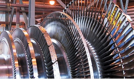
1. Biggest contributor. The low-pressure section may account for as much as 50% of the power produced by a utility-scale steam turbine. Courtesy: Bechtel Power Corp.
The push to lengthen LSBs comes not only from designers of large coal-fired power plants but also from developers of relatively smaller combined-cycle plants. There are significant differences between turbines designed for combined cycles and for conventional steam plants. Because feedwater heaters are not normally used in the thermal design of a bottoming cycle, for the same HP main steam flow the LP exhaust steam flow in a bottoming cycle can be up to 35% greater than in a comparably sized conventional turbine. In addition, bottoming plant designs may use duct firing to compensate for the reduction in gas turbine output at high ambient temperatures or for peak loading the plant, when doing so is economically justified. It has become quite common in the U.S. to use massive amounts of supplementary firing to almost double steam turbine output.
This article explores the fundamental features of modern LSB interdisciplinary (aerodynamic and mechanical) design, including the ever-increasing role of complex computational fluid dynamics (CFD) analysis. Our purpose is to investigate how turbine performance and operability are affected by the current trend of lengthening LSBs. The article concludes with a test case that delineates the real-world options available in selecting a suitable LSB system.
Aero design fundamentals
Conventional LSB design (subsonic inflow at the tip of the rotating blade) reaches aerodynamically acceptable limits sooner than blade mechanical limits. To address this shortcoming, turbine original equipment manufacturers (OEMs) have devoted considerable effort to understanding and improving the design of stationary and rotating blades. Changes from the existing traditional design boundaries, such as supersonic relative inflow at the tip of the rotating blade, have been evaluated during extensive analytical and experimental trials to gain user acceptance.
Only a fully developed 3-D stage flow analysis can provide an optimum blade profile capable of minimizing the losses from shock waves resulting from supersonic flow. The accuracy of modern 3-D analysis as a prediction tool has vastly improved—it can now account for nonequilibrium condensation flows with different steam wetness conditions and phase change variations.
For large LP LSBs, the relative exit Mach number is an important design parameter for assessing the operating range and exhaust losses. The longer the blade, the higher the exit Mach number, due mainly to a strong mid-stage pressure gradient.
Figure 2 shows a typical static pressure and Mach number distribution. The low pressure at the hub of the rotating blade (Ps1) produces a low root reaction, which eventually leads to flow separation within the rotating blade. The Mach number at the stationary blade exit (M1) has a very strong gradient, raising the inlet Mach numbers (Mw1) at the hub and tip of the rotating blade. The high pressure at the tip produces high absolute values of the exit Mach numbers at the hub of the stationary vanes and high relative inflow Mach numbers at the tip and hub of the rotating blade, which trigger shocks within the rotor passage.
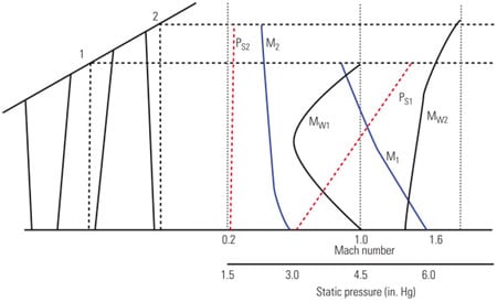
2. Tracking the field. Typical Mach numbers and static pressure distribution of a steam turbine last-stage blade. Source: H. Stüer, ASME GT2005-68746
A true 3-D design will influence the flow field to "control" this positive radial pressure gradient and avoid its detrimental effects. Several options are available, and can be used in combination, to achieve this goal.
The pressure gradient is mainly dependent on the streamline curvature and the swirl velocity. In a 2-D analysis, selecting a free vortex to control the pressure gradient will result in extremely twisted rotor blades for low hub-to-tip ratio and low hub reaction, thus generating high exit losses. A design based on using a forced vortex has the advantage of reducing the relative inlet velocity of the rotating blade.
However, achieving a true optimized flow field design with minimum losses requires an approach based on a 3-D analysis. Commonly used 3-D shapes are known as "blade lean" and "blade sweep." For a fixed hub configuration, a tangential lean is defined as the shifting of the stacking line tangentially to the pressure side. A blade sweep occurs when the stacking line is modified toward the inflow as the blade radius increases.
In some designs, the LSB lean is applied tangentially and axially. Combined with flow path contouring, the stationary vanes" tangential lean reduces the pressure gradient at the exit of the stationary vanes, raising the root reaction and allowing for a lower hub/tip ratio.
The stationary vanes" axial lean increases the vane-to-blade spacing at the tip, giving water droplets more time to accelerate before entering the rotating blade. This type of acceleration also mitigates the effects of erosion on the blade. In another application, the stationary vanes lean in the tangential direction, forcing the pressure side of the vane radically inward. Due to the action of body forces in this configuration, the increased pressure at the inner end walls causes a decrease in velocity and smaller pressure gradients, reducing turbine secondary losses. In a compound axial and tangential lean arrangement, the stationary vanes curve in the spanwise direction, and the pressure side surfaces intersect with the hub and tip endwalls at angles. This reduces the pressure gradients on the walls and consequently decreases secondary flow losses. A stator vane combining sweep and lean is the most advantageous configuration.
Depending on the design’s exit Mach number at the stationary blade hub, the profile is either convergent for subsonic and transonic inlet Mach numbers up to 1.3 or convergent-divergent for higher Mach numbers. A decision to use the convergent-divergent profile must be based on the results of a detailed 3-D analysis at design and off-design conditions rather than consideration of the exit Mach number. However, convergent-divergent passages for stationary vanes have not been used due to their sensitivity to varying exit conditions that occur during off-design operation.
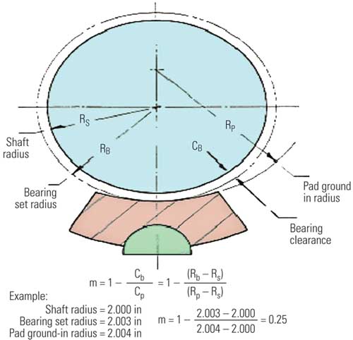
Design for long life
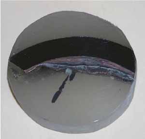
Mechanical constraints also play an important role in developing new, longer LSBs due to the extreme centrifugal forces that come into play. The allowable tensile radial stress value is the major limiting factor for blade length. Other limiting stresses include the bending stress resulting from steam forces in the blade root part and the tensile stress in the rotor caused by centrifugal forces (Figure 3). The mechanical design of longer LSBs must accommodate larger loads and changes in dynamic frequencies. It must also account for the method of interconnecting the rotor and the blade, decreasing vibration, and reducing leakage losses by the use of span dampers and blade shrouds.

3. Four-footer. These 48-inch steel last-stage buckets with curved axial entry dovetails reduce weight on the rotor. Courtesy: GE Energy
For the designer, the ultimate goal is to have the turbine operate at moderate stress while maintaining a conservative overspeed margin. Assuming a typical high-strength steel and an allowable stress of about 90,000 psi, the expected maximum exhaust annular areas for an LSB row would be 130 ft2 (for a 50-Hz application) and 90 ft2 (for 60-Hz service). These areas translate into blade lengths of 48 inches and 40 inches for 50-Hz and 60-Hz installations, respectively.
However, market pressure to increase LSB length has led developers to use titanium alloys rather than stainless steel to increase allowable stress design levels. Because the alloys are less dense (1.8 times) and much stronger than steel, they allow designers to create longer blades and larger annulus areas. For example, the yield strength of Ti-6Al-4V is the same as that of 17-4PH steel, but the weight of titanium is only 57% of that of steel. Another benefit of using titanium alloys relates to their greater resistance to wetness losses and damages. On the downside, titanium blades are much more expensive, and more brittle and prone to scratches than stainless steel. At present, steam turbine OEMs are applying lessons learned from the first generation of titanium blades as they develop (using a combination of aerodynamic and mechanical design techniques) the second generation, which have a 10% to 15% larger exhaust area.
3-D finite element analysis (FEA) has become an indispensable theoretical tool for validating the final mechanical design, particularly in determining the maximum average stress (required to define the overspeed limits) and maximum local stresses (indicative of the low cycle fatigue blade life and risk of cracking due to corrosion).
The curved-entry fir-tree is currently the most suitable structure for securing the longest LSBs. This configuration allows a slender wheel to be used and reduces centrifugal forces. Some manufacturers are using the fork-shaped root with a variable number of teeth, depending on the required load. Commonly encountered errors in parts machining and determining appropriate clearances between the dovetail hooks and the wheel create unequal distribution of the load and thus generate increased local stresses. The problem is exacerbated by increased blade length.
Staying connected
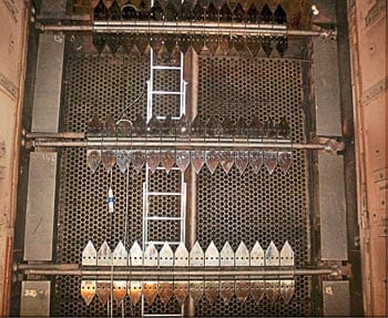
Aeroelastic instability, which occurs at extreme conditions either in the region of low steam flow or at high condenser pressure, produces significant flow separation at the blade hub, resulting in stall flutter and buffeting of the blades. To improve operational flexibility and provide greater rigidity, adjacent blades are linked together. The blades are integrally shrouded with the blade profiled body. To further increase the rigidity of the entire blade structure, the blades are coupled with a snubber, an integral tie-boss at the mid-span of the blade height. The use of titanium alloy blades with reduced damping properties makes a change in blade manufacturing from free-standing to interlocked construction an unavoidable necessity.
During turbine operation, the blade elastically untwists due to centrifugal forces, causing adjacent shrouds and snubbers to make contact. At rated speed, all blades are held together to form a continuous ring. Compared with conventional configurations, this arrangement exhibits more stable vibration characteristics: reduced resonance and vibration stresses and suppressed flutter. In one application, blades with integral shroud and tie-bosses situated at 70% of the blade height exhibit two to three times less vibrational stress than do free-standing blades (Figure 4).
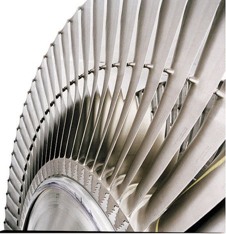
4. Joined at the hip. Blade shroud and span damper design in a 48-inch steel last-stage blade designed to operate at 3,000 rpm. Courtesy: GE Energy
The use of shrouds and snubbers does not come without penalties. Free-standing blades provide a more efficient peripheral water separation than do shrouded blades. The snubbers in the flow channel disrupt the flow, creating additional losses and increased erosion due to local wetness concentration.
Another difficulty encountered by the designers of advanced, larger LSBs is associated with the machining of the complex 3-D shape of the blade. The mechanical design has to determine the "no speed" airfoil shape that will achieve the aerodynamic design shape at nominal operating conditions. The mechanical design challenges center on converting the aerodynamic design into a machine-workable shape and providing sufficient margins for static and dynamic loads (Figure 5).
5. Twist and shout. Advanced aerodynamic blade designs also are a challenge to manufacture. Shown are a 40-inch, 3,600-rpm steel last-stage blade (L) and a 48-inch, 3,000-rpm bucket (R). Courtesy: GE Energy
It’s a dry steam
Almost 8% of the LP turbine losses can be attributed to a "wetness phenomenon" that mainly results from the following three causes:
- Nucleation of moisture from superheated steam in the phase transition zone (PTZ).
- Formation and release of liquid films on the blade surface within the PTZ.
- Two-phase flow from the LP turbine into the condenser.
The blade design must therefore provide protection against water droplet erosion.
The level of steam moisture varies widely in a steam turbine across the load range. Although the average steam wetness is not higher than 10% to 12%, the local steam wetness can be much higher, particularly in the tip region. The higher the tip speed, the more dangerous is the effect of the water that lags behind the steam and impacts the blade.
For very long LSBs, the conventional method for protecting against water erosion—use of Stellite strips brazed to the blade surface—presents new challenges. The Stellite strips create discontinuities in the blade profile, thus generating higher losses than in previous designs. Breaking of the Stellite strips could also cause local damage and changes in the dynamic characteristics of the blade. A very expensive alternative for removing the moisture is internal steam heating of the stationary blades. Another new method for protecting against erosion is laser hardening of the blades. This method delivers similar or better results for 17-4 pH material, compared with flame-hardening of conventional steels.
Cracking under stress
Stress corrosion cracking (SCC) is caused by the combination of tensile stress and a corrosive environment. Any material used for turbine blades and rotors must account for the effects of SCC. The less "aggressive" the environment, the higher the allowable operational stresses. Because advanced LSB designs exhibit higher levels of rotor and disc stresses, steam purity requirements must be more stringently controlled. Table 1 presents typical criteria conducive to the initiation of SCC.
Table 1. Cracking down. Conditions known to initiate stress-corrosion cracking of low-pressure turbine rotor and disc materials. Source: Bechtel Power Corp.
In evaluating SCC formation and propagation, it is critically important to account for the combined effect of material properties (steel cleanliness and yield stress), environment (oxygen, carbon dioxide, and chloride levels), temperature, and stress conditions. Yet the multiple possible combinations of increased tensile stress levels existing in large LSBs and poor steam purity during initial start-up make the forecasting of crack propagation difficult. Designers" only tools for SCC prevention are specifying low, conservative tensile stress for disc surfaces and reducing stress concentrations. Only actual field operation over time will determine the ability of the design to cope with the SCC phenomenon.
Exhausting conditions
At velocities above 600 ft/sec, the exhaust loss of a steam turbine is proportional to the square of the ratio of the volumetric flow through the turbine exhaust annulus area. At the appropriate backpressure conditions, better performance is achieved by selecting a larger exhaust area (either by decreasing the hub diameter and increasing the blade length or by reducing the blade length over a larger hub diameter). A larger exit area results in lower steam exit velocities and thereby reduces the kinetic energy of the steam leaving the turbine. The result is higher overall steam turbine efficiency. Table 2 lists large-size LSBs that are either in development or in operation for 50-Hz and 60-Hz applications.
Table 2. Long time coming. Steam turbine last-stage blade (LSB) development status. Source: Bechtel Power Corp.
The turbine thermal kit provided by the OEM contains information on LP exhaust losses in the traditional form of the "exhaust losses curve." This curve gives the specific enthalpy loss for an exhaust average steam velocity that depends on the turbine backpressure and/or steam flow. The use of curves also requires, for some OEMs, corrections for moisture content. Because the average steam exhaust velocity is a function of the volumetric flow for a given geometry, its value depends on both backpressure and steam mass flow. Figure 6 provides a number of exhaust loss curves for various exhaust areas for a sample of steam turbines from various OEMs. The increased exhaust loss at lower exhaust velocities (less than 550 ft/sec) occurring at low part-load conditions or high backpressure is due to the formation of a reverse vortex at the blade root.
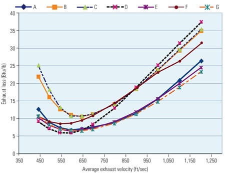
6. Adding up your losses. Typical exhaust loss curves from different turbine manufacturers. Source: Bechtel Power Corp.
Development of next-generation and often unconventional blade profiles, with large variations along the blade height, has produced considerable benefits in terms of the stage’s efficiency and reduced exhaust losses. Figure 7 illustrates the exhaust losses for two blades from different OEMs with almost identical exhaust and blade length area. You would be right to conclude that the more advanced 3-D profile design (curve A) leads to lower exhaust loss.
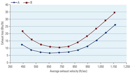
7. Different paths. Exhaust loss curves from two OEMs illustrate very similar exhaust area and blade length. Source: Bechtel Power Corp.
It should be noted that the total exhaust loss curve includes not only the losses associated with the LSB but also the contribution of the exhaust hood. Therefore, improving LSB efficiency must be associated with an appropriate, effective aerodynamic design of the exhaust hood.
Purchaser’s perspective
The continuous evolution of turbines in general and of LSBs in particular presents many challenges for engineering/procurement/construction (EPC) contractors responsible for selecting equipment, functionally integrating it with other power plant components within a fixed price and schedule, and guaranteeing overall plant performance to boot.
The EPC contractor must rely on his experience and expertise, and his previous project experience with turbine OEMs, when making technology selection decisions on behalf of the customer. As an example, Bechtel’s steam turbine experience covers a wide range of combined-cycle and conventional steam plants (Table 3) around the globe and gives a good snapshot of the typical technology selections made for these plants (Table 4). Two of the more recent projects have steam turbines operating at supercritical conditions.
Table 3. Experience counts. Bechtel Power’s combined-cycle steam turbine experience profile. Source: Bechtel Power Corp.
Table 4. A piece of the action. Recent Bechtel steam plant projects and the steam turbine supplier. Source: Bechtel Power Corp.
It’s considered good practice for the EPC contractor to conduct a thorough investigation of the various OEM offerings to ensure that the project’s basic performance objectives (for example, power output, heat rate, start-up times, reliability, and availability) can be met. The process also includes an independent technology assessment of the equipment’s operating history, engineering, and manufacturing processes. The turbine LP section performance metrics offered by the OEMs for a specific project should be normalized and reconciled with past performance of various types of equipment in a similar configuration offered by OEMs in other projects. Bechtel maintains a performance database of past projects that is routinely updated with information from field tests.
Due to the iterative nature of the turbine selection, all project stakeholders should involve themselves in the choice of optimal LSB length. And because the operation of the LP section is constrained by backpressure, the optimization process must include consideration of heat sink options. For example, it should be taken into account that the backpressure of an air-cooler condenser is typically higher than that of water-cooled condensing schemes, as well as more dependent on ambient temperature.
A systematic approach to LSB selection would entail running simulation programs to superimpose electrical demand, ambient conditions, and steam turbine-condenser performance on an hourly basis for an entire year. This analysis needs to be completed for several LSB sizes. Typically, a shorter LSB is less sensitive to large backpressure variations than a longer one, but it may not yield the best performance. The selection of the LSB will influence the number of LP modules, thus affecting the plant capital and operational costs. Besides the price of the turbine hardware, an additional LP module requires more building space, concrete, piping, wiring, instrumentation, controls, and the like. Operational and maintenance expenses are also increased by the additional hardware. A life-cycle cost analysis is the only way to properly compare design options.
Figure 8 shows the typical thermal efficiency values for all three modules (HP, IP, and LP) recorded during recent tests of a combined-cycle steam turbine. As the figure indicates, some LP turbine cylinder efficiency may reach 94% to 96%. In this analysis, the steam turbine power output for the fired case was 55% to 65% higher than for the unfired case. Although the HP and IP module efficiencies show only small differences between the fired and unfired cases, the LP module efficiency does change significantly. Its performance is directly related to the capacity of the heat sink, which determines the operating backpressure.
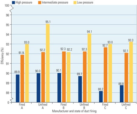
8. Do the math. Steam turbine module efficiencies for duct-fired and unfired cases, used to develop life-cycle cost comparisons. Source: Bechtel Power Corp.
Applying the fundamentals
The best way to illustrate these technical and selection fundamentals is with an actual case study of a project under development: a coal refuse–fired power plant with two circulating fluidized bed (CFB) boilers supplying steam to a single steam turbine generating a nominal 600-MW gross output. Because the fuel cost is very low, the most cost-effective cycle is a subcritical reheat cycle with main steam conditions of 2,400 psig and 1,000F and a 1,000F hot reheat steam temperature. Under the assumption that the electricity production cost will also be low, the plant is designed to operate in baseload mode, with no cycling duty features included. Although range of operation at partial load is a consideration for start-up and for operation in single-boiler mode, operating efficiency and alternate configurations only need to be evaluated at full load.
The turbine is specified as a condensing reheat design configured for down flow into a double-shell, single-pressure, water-cooled, two-pass surface condenser with a divided water box in the shell. The turbine exhaust pressure specified for the performance guarantee point is 2.5 in. HgA. The plant includes a single train of seven feedwater heaters: three LP, a deaerator, two IP, and one HP. The boiler feedwater pumps are motor-driven.
The LP turbine exhaust was initially configured as a four-flow design (two casings each with two-flow exhaust and 33.5-inch LSB length) even though an alternative design was investigated that was less expensive. The turbine OEMs were asked to provide quotes for a two-flow exhaust design (single LP section casing with two-flow exhaust), although there were concerns about exhaust velocity, blade stress, and vibration.
Evaluate field experience
One way to determine a design’s viability is to review any actual experience with the same or a similar design. The turbine OEMs confirmed that they had designed, built, and placed into operation turbines with the same or higher range of LP turbine exhaust velocities without experiencing technical or operational problems. The OEMs also confirmed that, while operating stress loadings for the turbine blades are higher for a two-flow design, they are still well below allowable stress values. Finally, the OEMs also stated that no vibration, instability, or other operational problems would be experienced.
One OEM was selected for further detailed review. Its two-flow design had five stages and a 40-inch LSB length with an exhaust velocity at the guarantee point of 975 ft/sec (vs. 675 ft/sec for the four-flow design). For the lower ambient temperature, lower exhaust pressure case, the two-flow exhaust velocity became almost 1,500 ft/sec, vs. 1,000 ft/sec for the four-flow design. This velocity exceeds the 1,100 to 1,200 ft/sec typically perceived to cause greater erosion of LSBs when combined with some level (10% nominal) of back-end moisture. As moisture builds up on the trailing edge of the stationary nozzles, droplets falling off at low velocities may impact the blades. At high velocities, however, the droplets are swept through the moving blade passages with little, if any, contact with the blades. The OEMs also confirmed that erosion problems are actually worse at lower loads and velocities.
Vibratory characteristics of the blades at running speed with such a high exhaust velocity were also a concern. The potential effect of shock waves due to steam exiting the LSB outlet at sonic velocity was reviewed. The OEM indicated that its CFD analysis for the standard diffuser design showed that subsonic flow exiting the LSB outlet only reaches a Mach number of 1.0 at a point away from the blading. This reduces the possibility of a shock wave forming that is strong enough to cause boundary layer separation. If separation does occur, the diffuser has been designed to isolate the boundary layer from the LSB. Review of a reference plant with similar operating conditions confirmed that separation, should it occur, is not a problem.
The shaft power output for the LP section is also about 5% higher for the particular two-flow versus four-flow designs that were reviewed: 301 MW vs. 286 MW, associated with a corresponding IP section reduction. The two-flow LP section has a relatively high steam loading for each blade. This results in a higher stage pressure drop, thereby requiring higher LP inlet pressure and, consequently, higher IP exit pressure. These higher pressure changes cascaded through the rest of the system; however, no technical issues were found.
A second check of industry experience, this time for shaft power output for opposed flow (HP, IP with a single two-flow LP section), revealed no problems for the units closest to the design being considered. Checking against the OEM’s reference plant, the steam flow loading on each stage blade for this proposed design was found to be approximately 20% higher, although the OEM confirmed the steam bending stresses for all stage blades are still within the allowable design limit. The steam bending stress represents a measure of a blade’s ability to withstand the stage power or loading from steam flow in the axial direction. The ratio of working to allowable stress is approximately 0.76 for the first stage and 0.27 for the last stage. This represents a safety factor of nearly 4 for the LSB.
The two-flow LP turbine configuration could be operated at a low backpressure during the colder months to slightly improve heat rate without much concern for high exhaust velocities. The best approach is to always operate the plant at or near the backpressure design point of 2.5 inch HgA during the winter by shutting off cooling tower fans and isolating compartments. The power output gain for the two-flow machine at the lower ambient temperature is only 800 kW (vs. 6,400 kW for the four-flow design) due to the relatively high backend velocity, which results in higher exhaust losses. The power plant–guaranteed output capacity matches the capacity in the grid interconnect agreement, and additional electrical output is of no immediate benefit to the owner. The owner can, however, apply for an incremental increase in output capacity to take advantage of potential improvements in electrical output capacity. Selecting the two-flow LP turbine at this time would preclude the owner from generating in the future almost 6 MW of additional power at lower ambient temperatures using the four-flow machine.
The two-flow LP turbine configuration would cost less than the four-flow design and have lower installation costs. However, the two-flow LP turbine design is less efficient than the four-flow design; its heat rate is higher by about 50 Btu/kWh at 100% load. The two-flow design’s reduction in efficiency was greater than anticipated; consequently, the boiler and other upstream and downstream equipment would need to be slightly larger and cost more than the four-flow design. Overall, the two-flow LP turbine design plant would cost less than the four-flow design.
Comparing the potential cost savings of the two-flow LP turbine design (offset by its higher heat rate and the lost opportunity to generate an additional 6 MW during the colder months) with the greater efficiency of the four-flow machine results in essentially a wash. Because the two-flow LP machine offered no significant benefits versus its potential risk (albeit small), the EPC project team and the owner decided to proceed with the more conventional four-flow LP turbine design.
The authors gratefully acknowledge Paul Kochis of Bechtel and Rudy Koubeck of Siemens Power Generation for their insightful review of the draft of this article.
—Dr. Justin Zachary is a principal engineer and project engineer for Bechtel Power Corp. He can be reached at jzachary@bechtel.com or 301-228-8764. Donald J. Koza is project engineer for Bechtel Power. He can be reached at dkoza@bechtel.com or 301-228-8757.