FIRE PROTECTION
Safeguarding coal-handling assets
Coal-fired power plants have millions of dollars invested in conveyor systems and train-unloading equipment. Consistent, reliable performance of this equipment is critical to maximizing plant performance and availability.
Effective routine maintenance is one way to help ensure that coal-handling equipment operates as designed. Another is installing adequate fire protection—especially if the plant burns dusty Powder River Basin (PRB) coal, which is prone to spontaneous combustion—and sophisticated monitoring and control systems. These systems also must be diligently tested and maintained.
Rely on eyes
A key ingredient of any routine maintenance program should be a comprehensive system "walkdown" by trained personnel, once per shift. Experience indicates that, regardless of the level of electronic monitoring, visual inspection of equipment—while it is operating—significantly reduces failures and improves performance.
Personnel should be trained to distinguish normal operation from abnormal operation as well as how to identify and pinpoint potential problems. In the case of coal-handing equipment, inspections should include:
- Listening to all conveyor drives for any unusual noise or vibration.
- Checking for any coal spills (Figure 1) or excessive dust accumulation and identifying the source.
- Remembering to check the seals and loading tables of transfer chutes and feeders.
- Checking scraper performance for carryover and spillage. Scrapers also should be inspected to ensure that they are adjusted properly, not worn excessively, and not contributing to excessive conveyor wear.
- Carefully eyeballing remote alarm panels, heating and ventilation systems, and dust-collection or -suppression equipment (Figure 2).
- Checking that all fire-protection system valves and fire doors and barriers are in the correct position, and documented as such.
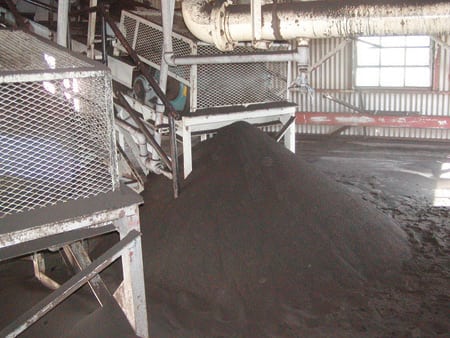
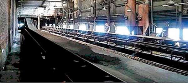
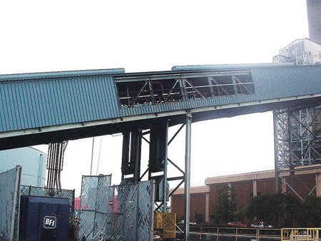
1. Poor housekeeping. Coal accumulating at the tail of a conveyor not designed to handle Powder River Basin coal is an extreme fire hazard. Source: POWER magazine
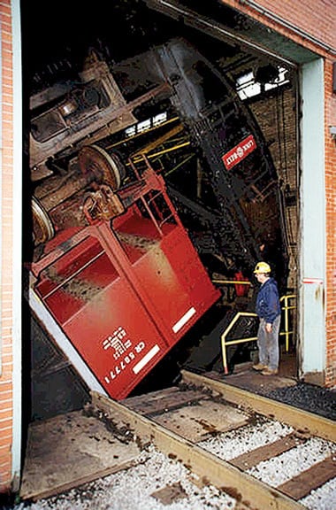
2. Easy dump. A properly designed dust collection system is a must for every rail car unloading station. Courtesy: DOE
Routine maintenance is made more difficult by poor housekeeping and bad lighting. Applying a coat of bright paint to equipment and structural surfaces is a cost-effective way to increase visibility.
Keep it clean
Routine cleanings and washdowns of accumulated dust make coal-handling systems less susceptible to fire. Automating these processes is simple and reduces their cost. Good housekeeping also minimizes deterioration and corrosion of structural steel and other metal surfaces that are in prolonged contact with moist coal. Washdown systems should be installed in crusher houses, transfer houses, scale houses, and coal-sampling facilities. Their effectiveness should be monitored on an ongoing basis by plant operators.
Although it’s important to keep the areas around all coal-handling equipment clean, it’s imperative in the case of vibrating reclaim feeders, plow feeders, and receiving feeders used to unload trains. Field experience indicates that allowing PRB coal to remain in these areas for one week makes spontaneous combustion much more likely.
A reliable control system can ensure that all feeders are used regularly and that plow feeders are allowed to travel the entire length of the slot. The system also should be able to maintain a relatively constant feed rate. Doing so—as opposed to starting and stopping the feed—will decrease O&M expenses, reduce seal and scraper maintenance requirements, and extend the life of conveyors. But don’t rely completely on the control system. Feeders should be visually inspected while operating to ensure that they are working as designed. When inspecting a plow feeder, confirm the control system’s indication that it is traveling the full length of the slot.
Most controls for cascading conveyor systems shut the system down to avoid a large spill should a conveyor fail for any reason (Figure 3). Because this is critical to limiting the spread of a possible fire, conveyor controls should also be checked routinely.
3. Inviting problems. The need to remove the siding from a conveyor to increase ventilation is a sign of a poor design. Source: POWER magazine
Keep it cool
Because coal is extremely abrasive, any that comes in contact with rotating drive systems, pulleys, and bearing surfaces could generate enough heat to start a fire. An effective, scheduled lubrication program can reduce this risk as much as it reduces equipment maintenance costs.
The role of lubrication in fire prevention is particularly important for motor bearings, gear boxes, conveyor idlers, and fire system valve stems and stem nuts. Dirty, oil-starved valve stems and nuts need to be replaced—at great cost—more often, and they make it more difficult to isolate pumps and piping systems for maintenance.
Fire reveals safety gaps
The U.S. generation industry’s ongoing wholesale shift to PRB coal has elevated the importance of fire safety. Cleanliness levels, and practices and systems for containing spills and suppressing dust that were adequate for a plant when it burned Eastern coal, must be improved as part of the fuel switch.
Obviously, automatic fire-protection systems are part of the safety solution. But even a 100% reliable system and a world-class housekeeping program may not prevent all plant fires. Human error, shoddy maintenance, and/or protection equipment that is poorly designed or uncalibrated can create an unsafe condition that goes unnoticed until it is too late, as the following story of a plant fire illustrates.
The plant in question was five years into a switch to PRB coal. Everyone on site at the time knew full well the safety hazards such a major change created, and management had taken appropriate steps to reduce them. For example, the engineering and maintenance departments had proposed and completed numerous upgrades and modifications of the plant’s coal-handling facilities and fire-protection systems and installed a dust-suppression system tailored for PRB coal.
The fire was triggered by the unloading of a coal train by a receiving system with a capacity of 3,000 tons/hour. The coal was hot, and as it was being unloaded, a tail pulley bearing on a 500-foot conveyor between the unloading pit and the stacker tower failed, sparking a fire. Alarms sounded in the plant control room and the stacker tower. The plant’s Emergency Response Team (ERT) was activated and sent to the location.
Immediately, the ERT realized that the automated fire-protection system had failed to deliver sufficient water to the upper levels of the conveyor. Their first assumption was that spray valves did not open as designed, but that was not the case. One eagle-eyed team member then noticed that a manual isolation valve in the fire system was in the closed position. After he opened it, water started to flow. But by then the fire had spread almost to the stacker tower.
The ERT ended up having to extinguish most of the fire with hoses. Fortunately, no one was hurt, but the unloading system was essentially totaled. It took two months of around-the-clock effort and $1.4 million to return it to service. Luckily, the system that was destroyed was one of two at the plant. If it had been the only one—as is often the case—the fire’s toll, including lost generation sales, would have been much heavier.
Identifying the culprits
The closed isolation valve was the first target of the post-fire investigation. The best guess was that it had been mistakenly left in that position following the most recent maintenance outage, a few months earlier. To be sure that no other manual valve had been left shut, plant management initiated an immediate audit of every valve in the fire-protection system and drew up procedures and policies for repeating the audit weekly. The importance of this program cannot be overstated. It not only validates the reliability of the fire-protection system, but it also helps to familiarize personnel with the location of all system valves.
The fire-protection system’s poor performance was the next issue examined. The postmortem determined that there were three contributors to the low flow: piping leaks, widespread pluggage of sprinkler heads with rust and scale, and fire pumps of insufficient capacity. The existing pumps were upgraded, and additional pumps were installed to increase the system pressure.
A new maintenance guideline for conveyor fire protection systems at the plant was instituted as a result of the investigation. It required full-flow testing of all such systems twice a year, including a visual inspection of every sprinkler head during full discharge. After one year under this regime—following the plugging of the piping leaks and clearing of the plugged sprinkler heads—management decided to double the frequency of testing from semi-annually to quarterly. This program proved capable of ensuring reliable system performance.
The third question that the investigation sought to answer was why the fire was able to spread so far before an alarm sounded and the sprinklers activated. Testing of the fire-protection system indicated that it needed more flame detectors over a wider area and that the detectors needed to be more sensitive. The quarterly performance tests call for all detectors to be activated by an actual heat source. During the tests, all alarm systems and associated automated conveyor controls are tested and documented for proper function. Any failures or incipient problems identified are given a P-1 priority, for immediate correction and repair.
So far, so good
Two years after the fire, the entire plant was thoroughly audited by its insurance company, which called the new fire protection policies and procedures "the most effective program we’ve ever encountered." As proof of that, the plant has never since experienced a fire of similar scale. A few minor fires have occurred, but they have been detected and automatically extinguished so quickly that equipment damage and risk to personnel have been insignificant.
—Contributed by Timothy C. Earney, senior consultant for utility fire protection at Air Control Science Inc. He can be reached at 636-667-9869 or tearney@aircontrolscience.com.
MECHANICAL
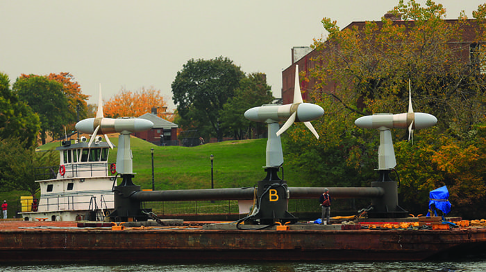
Giant wind turbine hard to bear
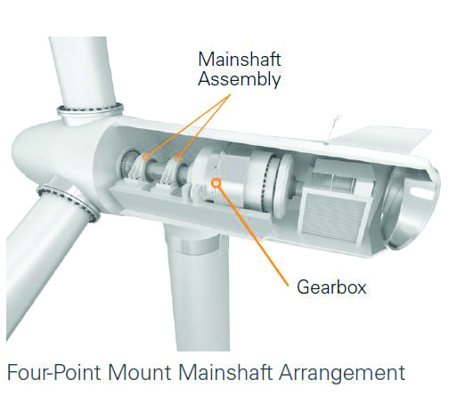
All wind turbines are large, but the REpower 5M wind turbine is huge. Built and marketed by REpower Systems AG of Hamburg, Germany (www.repower.de), the 5M (Figure 4) stands 394 feet high and produces 5 MW of power. With three blades of 413-foot diameter, it is one the largest and one of the most efficient wind turbines in the world. Two of the toughest tasks involved in creating the 5M were designing and manufacturing a bearing system for the 59-inch-diameter shaft that supports the machine’s three-bladed rotor, which weighs in at over 130 tons.
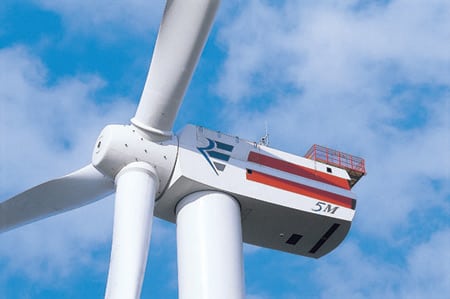
4. Heavyweight class. The size, efficiency, and capacity of REpower’s 5M wind turbine set new standards for the worldwide wind power industry. Courtesy: SKF
Sharing the load
Wisely, REpower outsourced these tasks to one of the world’s top bearing specialists—SKF. Right off the bat, SKF knew this was an unusual job because, although the cast-iron shaft would support the massive rotor, the customer decided to make it hollow—to meet weight, cost, and performance requirements.
Later, working closely with REpower designers, SKF engineers came up with a way to eliminate the influence of positional and deflection-related errors on rotor movement. The system that the two teams devised uses two SKF roller bearings to support the shaft: a CARB-model toroidal unit in the nonlocating position and an axially locating spherical unit in the locating position. This arrangement offers high load-carrying capacity and the lowest possible total weight (bearing plus housing) for a two-bearing system.
Size mattered
To design the bearing system, SKF used an in-house dynamic simulation program called "Beast." Serving as a virtual test rig, Beast eliminates the need to perform long and costly experiments on an actual test rig. It also produces more accurate results more quickly. On the REpower 5M job, Beast evaluated how the incline of the unit’s shaft would influence bearing behavior. The final system—a bearing with an inside diameter of 59 inches and a weight of almost 6,000 pounds—should be considered a milestone in the field.
Further work involving the use of finite element method (FEM) calculations was needed to determine the interference fit on the hollow rotor shaft. For smaller bearings, experience has yielded standard recommendations that can be found in SKF catalogues, which are online at www.skf.com. The use of Beast and FEM proved invaluable because the characteristics of large bearing systems are totally different than those of smaller ones.
The size of the bearing also taxed lubrication requirements. It’s well-documented how grease behaves when covering a bearing with a diameter of 20 inches. But understanding how grease would work on a 59-inch bearing represented a new frontier. Lubrication specialists at SKF set out to discover whether grease alone would be sufficient to cover all the relevant surfaces and whether gravity would take it to the bottom of the housing. Initially, the housing was designed to accommodate lubrication with oil as well as grease. Subsequent inspections indicated that grease alone worked well, so the final housing was made simpler.
Can’t buy it? Build it
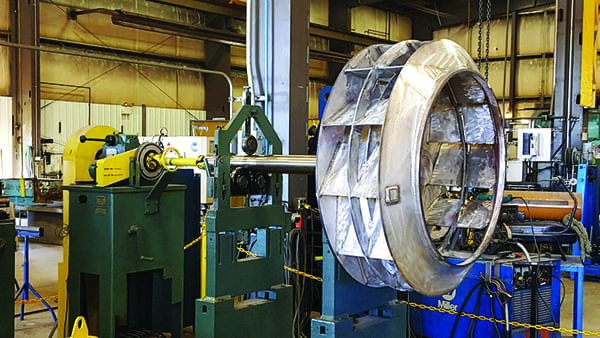
Another challenge that SKF’s bearing specialists faced involved assembly and installation of the two huge rotor shaft bearings. There were no commercially available induction heaters capable of uniformly heating the 6,000-lb CARB bearing and the 7,300-lb spherical roller so they could be joined. To enable proper heating of the bearings and their two 17,600-lb housings, SKF had to design and have built a custom 1,000-kVA induction heater (Figure 5).
5. Roll your own. A custom-designed 1,000-kVA induction heater was used to help mate bearings and their housings during turbine assembly. Courtesy: SKF
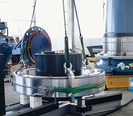
Because the roller set in the CARB bearing weighs almost 1,800 lb, it had to be specially clamped during heat-up and assembly (Figure 6). Without induced safe clamping, the weight of the rollers would cause them to clamp loosely between the inner and outer ring, which could damage the raceways. This kind of loose clamping also occurs in standard-size bearings mounted vertically, but standard-size bearings weigh much less, so it does no harm. However, to improve quality assurance, SKF also clamps smaller bearings to ensure safe mounting.
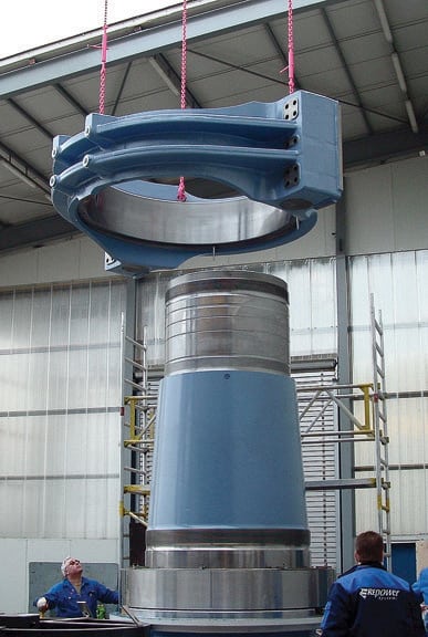
6. Tight fit. The 17,600-pound CARB housing being lowered onto the hollow cast-iron shaft. Courtesy: SKF
Axial fixation of the bearings posed another major hurdle. Fixation is usually done by shaft nuts, but the frictional moment on a thread of 59-inch diameter simply would have been too enormous. SKF solved the problem by designing a novel safety split nut, the largest ever made. Called the HMS lock nut, its most notable feature is the absence of a keyway in the shaft. This makes the overall design more robust and reduces manufacturing costs. The system is easy to mount and open for maintenance and repair, and there are no problems with fretting corrosion when dismounting.
Destined for a life at sea
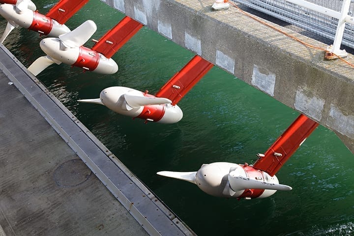
The first 5M wind turbine was erected off the coast of Brunsbüttel, Germany, and connected to an onshore grid in February 2005 as a pilot project to evaluate its design. REpower went with an offshore site for the unit’s debut because company engineers believe that wind at sea is slightly stronger and much more reliable than wind on land (Figure 7).

7. No pain, no gain. REpower hopes to site a fleet of 5M wind turbines exclusively in the harsh marine environment. According to company engineers, the greater strength and frequency of offshore wind can produce twice as much power as an identical onshore installation. Courtesy: SKF
Together, the differences mean that an offshore turbine would produce twice as much electricity as an identical unit on shore, say REpower engineers. Consequently, the Brunsbüttel installation is only a dry run to prepare for a series of 5M installations out at sea. The first proposed site—part of the Talisman DOWNVIND project supported by the European Union—is 18 miles off the Scottish coast in 150 feet of water.
Knowing up front that the 5M was destined for an inhospitable environment, SKF took extra care during the design, manufacture, and installation of its rotor shaft bearing system. The system has excellent corrosion protection, redundancy in many components, and continuous electronic monitoring of critical components. In short, it has been engineered for long-term reliability.
—Contributed by SKF (www.skf.com).