Determining the relevance of power generation equipment’s field experience requires special expertise and dedicated research. The continuing evolution of technology, manufacturing processes, and quality control techniques demands updating the old approach to validating “proven technology.” Because equipment manufacturers’ product development never stops, it is difficult to determine what represents “pertinent” operational experience.
For example, although two gas turbines may have the same model number, they operate differently if one has been modified in the factory or in the field and the other has not. How to accurately evaluate the results of this experience when making a purchase recommendation is the challenge faced by all engineering/procurement/construction (EPC) contractors.
Original equipment manufacturers (OEMs) have significantly improved the ratings of prime movers, steam generators, and environmental control systems over the past few years. Thanks to technological breakthroughs, combined-cycle power plants are now pushing the 60% net efficiency (lower heating value) barrier. Similarly, coal-fired plants powered by boilers operating at supercritical and ultrasupercritical steam conditions have increased their thermal performance while decreasing their output of pollutants.
These technology improvements are a boon to power plant planners but represent a dilemma for EPC contractors, who must determine how to properly evaluate new and upgraded hardware. On the one hand, using the newest and most efficient turbine makes it easier to cope with rising fuel costs and growing pressures to reduce CO2 emissions. On the other, early adoption of advanced turbine technology could put the reliability and availability of a plant at risk—and expose the EPC contractor to penalties if the turbine doesn’t perform as advertised.
Power plant owners have always tried to avoid ordering “serial number one” of any device; for newer equipment, they have typically insisted on a track record of 8,000 to 16,000 operating hours before considering it “proven” technology. But, as all power engineers know, every plant is unique. In many cases, equipment modifications and supplier-recommended O&M practices continue to be implemented even after a plant has been commissioned. How can a contractor make a reasonable evaluation of equipment whose performance is a moving target and that may have been customized to meet site-specific needs?
Compared to what?
Technologies mature through incremental changes, yet technology breakthroughs occur only through revolutionary advances. For example, when a gas turbine supplier introduces a new model, it falls to the owner and EPC contractor of a proposed plant to determine whether the improvements incorporated in the new unit are significant enough to warrant a fresh assessment of the risks and rewards of using that particular turbine line.
These decisions must be informed by very specialized expertise. Ideally, they should also be based on a comparison of the operating experience of the new model to that of its predecessors. However, such comparisons cannot be made if the new model or a similar unit has yet to enter commercial service. To further complicate matters, the cumulative operating hours of a particular turbine model as a measure of its technology’s maturity may be irrelevant to evaluating the latest gas turbine uprate, because suppliers introduce hardware modifications on a continual basis.
The situation is even more complicated in the case of steam turbines. With the exception of the last three blades in its low-pressure section, the hardware of a modern large steam turbine is specifically designed to the flow and pressure conditions of a given application. Those steam conditions, in turn, are a function of fuel and site conditions, such as ambient temperature and humidity, and the kind of condenser used.
Bechtel Power Corp. has developed a process for evaluating gas turbines (GTs) and steam turbines (STs) that fairly identifies the risks and rewards of adopting new turbine technologies. This article presents several examples of such evaluations—and their bases and established best practices—made in the course of developing and/or executing more than 30 advanced combined-cycle power projects and five subcritical and four supercritical steam plant projects over the past seven years. The following discussions should be helpful to OEMs trying to understand how EPCs choose turbines and to plant developers seeking guidance on making similar decisions.
Evaluating new gas turbines
The gas turbine has been a mainstay of U.S. power generation for more than two decades now. The fact that several makers of GTs continue to introduce new and/or uprated units suggests that demand for gas-fired generators will continue. For large GTs, the industry uses a letter designation to identify the machine’s technology class—an overall measure of its air volumetric flow, its compressor pressure ratio, and, most importantly, its firing temperature. During the 1980s, E-class gas turbines ruled the market. F-class GTs became available in the early 1990s and represent the majority of units operating in the U.S. today.
The newest turbine classes, labeled G and H, change the game of how the main combined-cycle components interact. The G and H technologies create an inseparable thermodynamic and physical link between a combined-cycle plant’s primary (GT) and secondary (ST) power generation systems by using steam (in lieu of air) in a closed loop for turbine cooling. (See POWER, June 2007, p. 42 for a tour of Siemens Power Generation’s G-class machine, and POWER, September 2007, p. 44 for coverage of the first U.S. deployment of Mitsubishi Heavy Industries’ G1 unit.)
Significant uprates in power output and thermal efficiency from one technology class to the next are the result of major design and manufacturing improvements. Figures 1 and 2 compare the improvements in power output and heat rate, respectively, within and between technology classes achieved by two different OEMs. Both suppliers attributed the uprates to the use of an evolutionary design process with a “proven, existing design base,” as well as to their accumulated experience. That may be so, but such a broad explanation does nothing to help prospective buyers quantitatively evaluate turbine upgrades either as they are announced or afterward.
Rating uprates
Gas turbine OEMs routinely release evolutionary upgrades to improve the thermal and/or mechanical performance of their existing fleet. Some upgrades are optional and available at a price. Others are handled as warranty items. In either case, the question for a power project developer or contractor attempting to evaluate an upgrade is whether to consider it a mere “tweak” or significant enough to constitute a brand-new model of gas turbine.
Good examples of this quandary are the GE 7FB and Siemens-Westinghouse 501 FD turbines, each of which offers thermal performance superior to that of the original F-class machines. As Figures 1 and 2 indicate, although the power output and heat rate improvements within the F class over a period of 15 years amounted to less than 10%, they were not insignificant. The major changes to F-class machines included increases in airflow and compressor pressure ratio, and higher firing temperatures made possible by the development of advanced materials and their use in turbine blades and nozzles. How should these more revolutionary uprates be handled when evaluating turbine alternatives?
1. Up the ante. These bars show the class-to-class gains in the power output of gas turbines from two different manufacturers. The data are for turbine operation at ISO conditions. Source: Bechtel Power Corp.
2. Pushing efficiency. This chart compares the class-to-class heat rate improvements of gas turbines from two different OEMs. The data assume turbine operation at ISO conditions. Source: Bechtel Power Corp.
Pieces of a whole
Whether an uprate is evolutionary or revolutionary, the process for evaluating it must remain the same—the separate vetting of each turbine component affected, followed by an analysis of the interactions between them. Following are some examples that illustrate the challenges facing anyone attempting to do an appraisal of a complete turbine system.
Compressors. One of the most common ways to increase the airflow through a GT compressor is to open the unit’s inlet guide vane (IGV) angle slightly. Using detailed data on compressor surge margins from operating experience at various ambient temperatures, many manufacturers have tweaked IGV angles beyond their initial setting. Additional gains in compressor performance can be achieved by modifying the aerodynamics of the two stages following the IGVs. Though this practice can increase a GT’s power output, it also may reduce the compressor’s surge margin and negatively affect its performance at high ambient temperatures.
The performance benefits of increasing mass flow at 104F will not be as great as those at ISO conditions (59F). In this case, the gas turbine evaluator should consider pertinent only the experience of those turbines in the fleet on which the compressor modifications have been implemented. Often, suppliers’ published operating hours represent the cumulative experience of all turbines with same model number. They therefore do not account for differences between the units, in terms of either airflow or the status of recommended hardware design modifications.
Another way to improve the efficiency of a GT is to increase its compressor’s pressure ratio. With the advent of sophisticated computational fluid dynamics techniques, it has become possible to raise pressure ratio without increasing the number of compressor stages. This option maintains the engine length and bearing locations but requires the use of better materials for the compressor’s last-stage blades, which are exposed to higher temperatures. However, a higher compressor discharge temperature also requires a detailed reevaluation of both combustion system dynamics and the air-cooling circuits of all turbine sections.
Combustion system. The dry low-NOx (DLN) combustor is another GT component that suppliers are constantly seeking to improve. Ever-lower air pollution limits have pushed turbine OEMs to develop combustion technologies that can now limit the NOx emissions of a turbine firing at 2,400F to single-digit ppm levels.
Despite extensive validation programs, this evolutionary process has been accompanied by many setbacks and field problems (for example, combustion oscillations). Due to the nature of lean premix combustion, DLN burner systems are sensitive to even minor changes in their geometry or cooling air patterns. Implementation of any evolutionary modification of this sort should be accompanied by thorough rig testing and field validation. Technology demonstrations should address only the cumulative experience of units with identical combustion system geometry and the same control software.
Firing temperature. The most common way to increase the power output and efficiency of a GT is to raise its firing temperature. For many years, this was a gradual process marked by step improvements of 20 to 30 degrees F. Recently, however, even greater increases in firing temperature have been made possible through the use of sophisticated nickel-based superalloys (single-crystal nozzles and blades) and elaborate air-cooling schemes.
But determining whether a particular gas turbine should be considered proven technology still requires obtaining performance and availability data from units operating at the same, or nearly the same, firing temperature. The problem here is that turbine firing temperature (TFT) must be calculated (as opposed to measured), and different turbine suppliers define the turbine inlet temperature (TIT) needed for the calculation differently. For example, the European GT suppliers—Alstom and Siemens Power Generation—use the theoretical ISO 2314 definition of hypothetical TIT, which assumes that the entire compressor inlet flow enters the combustor, making the calculation possible. Other manufacturers define the TIT as the gas temperature at the inlet of the first turbine rotor. The calculation of this TIT is more difficult, because it is necessary to know several air-cooling flows, which are considered to be manufacturers’ proprietary information. Because the final TFT or the true TIT value is determined during the final stages of GT commissioning (both vary from engine to engine), a practical comparison approach should consider gas turbines with a TIT range of ±10F.
Dimensional scaling. Turbomachinery manufacturers commonly use this time-saving technique to create different-size (usually larger) components with the same positive attributes as a previous part. If the basic rules of scaling are followed (for example, using a linear factor of speed ratio for dimensions and a square factor of speed ratio for flow), the new component’s basic mechanical safety margin and aerodynamic design remain unchanged.
Unfortunately, combustion dynamics and heat transfer characteristics cannot be scaled. As a result, critical areas of turbine subsystem development (such as cooling schemes) must be analyzed and validated in every scaling case—just as mechanical tolerances, surface finishes, and tip clearances must be. An important criterion for evaluating a scaled turbomachinery component is determining how the implemented changes affect the integrity of the original design.
Validation methodology. The process of developing a new GT requires individual testing of all of its major components. Despite developers’ extensive multi-phase validation and integration programs, all new GTs have presented many first-of-a-kind technical challenges upon their debut. OEMs, EPC contractors, and insurance carriers have paid a hefty price to correct turbine problems under actual field operating conditions.
In response, several leading GT manufacturers—Alstom, Siemens Power Generation, and Mitsubishi Heavy Industries (MHI)—have built in-house testing facilities to evaluate the performance of their new units at load in a completely controlled environment, to identify potential problems in a unit before it reaches market prematurely, and to reduce development time and cost. (See POWER, October 2007, p. 32 for a full description of MHI’s full-scale test facility for integrated gasification combined-cycle systems.)
Siemens and General Electric have also pursued an alternative approach to gas turbine testing: using a power plant as a validation site. In Siemens’ case, E.ON—the owner of Irsching Station in Germany—gives the company open access to Unit 4, a 530-MW combined-cycle facility to be powered by Siemens’ SGT5-8000H gas turbine (Figure 3) when it comes on-line in 2011. In exchange for the opportunity to “road-test” and implement changes to the new GT before it is introduced, Siemens will possibly offer commercial benefits to the host, E.ON. The table (p. 57) locates the testing facilities of the major GT manufacturers.
Major OEM testing facilities for advanced gas turbines. Source: Bechtel Power Corp.
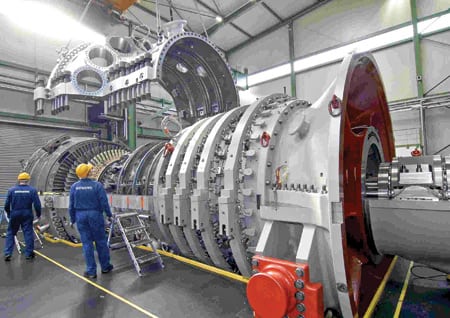
3. We’re number one. Siemens Power Generation is calling its new SGT5-8000H the world’s largest (340 MW) and most efficient gas turbine. As part of a 1 x 1 combined-cycle configuration, it is expected to produce 530 MW at a thermal efficiency of more than 60%. The photo shows an SGT5-8000H leaving Siemens’ factory in Berlin. Courtesy: Siemens Power Generation
GT evaluators should be aware that many of the improvements being incorporated into H-class designs are already flowing back to F and G class units. The most recent examples are the GE 9FB’s implementation of many GE H system features (Figure 4), and the MHI M701G2’s incorporation of M501H technological enhancements, giving it performance superior to that of the original M701G.

4. Industry leader. A GE 50-Hz Frame 9FB awaits shipment to a project site in Spain. The 9FB sports thermal efficiency approaching 58% in combined-cycle mode. Courtesy: GE Energy
Even if small modifications made to a GT’s design are thought to have limited impact on its performance or behavior, there is always the chance of an unforeseen cumulative negative effect on both due to the mechanical and thermodynamic interaction between individual components. Any evaluation process must consider this possibility.
Field data is essential
A key goal of any GT evaluation must be a thorough understanding of both the financial objectives of the proposed project and its desired performance levels (net power, heat rate, emissions, reliability, availability, and the like). Regardless of whether a new or upgraded GT is being considered, the selection process must include a technology review of the offering to evaluate the nature and significance of changes from previous models with a good operating track record.
The analysis must include details of the supplier’s model validation process as well as available data on the model’s performance. In many cases, the review also covers various aspects of quality control in the engineering and manufacturing processes. The performance data offered by prospective suppliers of a specific project must be normalized and correlated with the performance of the same type of GT documented on previous projects.
Bechtel bases its GT evaluation on a performance data bank that was created over time and is constantly updated with information from field tests (Figure 5). The establishment of a machine’s credentials must be based not only on its model nameplate but also on a complete list of implemented modifications.
5. Walking upright. The evolutionary scale of F-Class gas turbine technology. Source: Bechtel Power Corp.
To understand why this is important, take a close look at Figure 6, which shows the thermal performance of 37 GTs from four OEMs installed on various recent projects. Note that eight units did not deliver the guaranteed power output, and that 11 did not meet heat rate guarantees. These real-world experiences must play a role in any purchase decision.
6. Difference of opinion. This chart compares combustion turbine guarantees from various manufacturers’ actual test results for power output and heat rate. Source: Bechtel Power Corp.
Evaluating new steam turbines
The development of advanced steam turbines is being driven by demand for combined-cycle plants and for a new generation of solid fuel–fired plants. For combined-cycle applications, STs have followed the same evolutionary path as heavy-duty GTs. Today, the interdependency between gas and steam turbines has become even more pronounced with the advent of G and H class GTs (Figure 7).
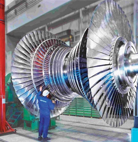
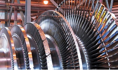
7. Low-end power. This low-pressure steam turbine from Siemens was installed at a 1,000-MW lignite-fired plant in Niederaussem, Germany. Courtesy: Siemens Power Generation
Worldwide, most steam turbines destined for power coal-fired plants are being designed to operate at supercritical (SC) or ultrasupercritical (USC) temperatures and pressures. In the U.S., all proposed coal plants have main steam pressure and temperature values well above supercritical conditions for the sake of improved efficiency and to reduce the plant’s carbon footprint. Most coal plant developers now seek net plant efficiency (high heating value) in excess of 42%.
Early efforts to raise the overall efficiency of a steam turbine focused on improving its high-pressure (HP) and intermediate-pressure (IP) sections. But increasingly, manufacturers also aggressively sought to upgrade the low-pressure (LP) turbine, which in many cases accounts for 50% of the ST’s power output. Today, a key development objective is to increase the size of the turbine’s last-stage blades (LSBs), thereby reducing the number of LP modules required and boosting power output at lower condenser pressures.
On the one hand, the trend in advanced ST design is toward greater standardization of the number of modules and their sizes as a way to reduce costs and accelerate development schedules. But on the other, the only way to improve thermal efficiency is to custom design the blading of each turbine section, with the exception of the last three stages of the LP section. This can be accomplished only by using highly computerized design and manufacturing methods.
Understanding what “proven technology” means in the context of advanced steam turbine design requires the supplier and customer to discuss development trends and to compare target ST specs to those of operating units. Legal and commercial agreements between the parties must overcome the barriers of proprietary information disclosure by having a structure that protects turbine manufacturers but allows the release of sufficient technical information to allow turbine buyers to conduct a meaningful technical evaluation. Several examples follow.
HP-IP blade design. The blades of an ST are the components that receive the most attention in any technical evaluation. Significant effort is expended to optimize blade design, which has a direct and powerful effect on the efficiency of a turbine’s HP and IP sections.
It is now customary to use a full 3-D design to account for all blade profile and leakage losses and other secondary effects. Because HP and IP blades are relatively short, large end-wall losses occur at the hub and the shroud. A stage efficiency improvement of 2 percentage points can be obtained by modifying the conventional cylindrical blade design using 3-D design techniques to bend and twist blades at their hub and tip. Another way to improve HP-IP blading is to use variable reaction for each stage in the blade path length instead of constant reaction. Improvements of 1 percentage point and higher in the module efficiency have been reported.
HP-IP configuration. A key decision centers on whether separate or integral HP-IP modules should be used because the module count has a big effect on overall ST cost. Several manufacturers suggest that the use of a single, opposite-flow combined HP-IP module has cost and project schedule advantages. This type of arrangement has been used successfully for STs rated at up to 600 MW (gross). If the rotor can be shipped preassembled into an inner and outer casing, as one design indicates, shorter erection and commissioning times are possible. The advantages offered by integral HP-IP modules give manufacturers an incentive to propose this arrangement for STs with even higher ratings, around 800 MW.
An important criterion for evaluating the technology requires review of IP exhaust losses at different operating and pressure-setting conditions. In this configuration, there is a single flow of steam in the IP section, so the velocity of the exiting steam rises—as do losses. In some installations a conventional double-flow IP flow will allow a more equitable flow distribution when each IP flow will be connected to one double-flow LP module.
Seals. In addition to using conventional, noncontact labyrinth seals, ST manufacturers have introduced new sealing technologies in an effort to further reduce leakage losses. Several sealing methodologies used in GTs, such as abradable seals and brush seals, have found their way into ST applications. Such designs could reduce leakage flow by 20%, compared to the use of uncoated seals.
In addition, brush seals are becoming standard features in advanced STs—particularly in the HP and IP modules of SC and USC turbines. In this type of application, the leakage flow is reduced by 50%, compared with that of a conventional seal. The absence of any clearance between the brush and the surface of the part reduces leakage by 70%, potentially improving overall turbine efficiency by one-half percentage point. End users are advised to evaluate the OEM’s specific experience with brush seals in each turbine section.
LP turbine LSBs. The LP turbine’s last-stage blades are a key element in ST design because they determine the turbine’s performance, dimensions, and number of casings. Increasing the length of the LSBs would reduce the number of LP modules required.
To overcome the shortcomings of conventional, subsonic LSB design, ST manufacturers have devoted considerable effort to understanding and improving the design of stationary and rotating blades. Changing existing traditional design boundaries—such as supersonic relative inflow at the tip of the rotating blade—has been evaluated by extensive analytical and experimental trials with an eye to improving user acceptance. Mechanical constraints also play an important role in the development of the new generation of longer LSBs. Market pressure to lengthen LSBs has led developers to use titanium alloys instead of steel.
In many cases, to reduce cost and development time, dimensional scaling was used to convert the design from one rotational speed to another. However, dimensional scaling, as discussed above in the context of gas turbines, cannot eliminate the need for hardware validation in rig tests or for running actual field applications for a substantial amount of time.
Two examples of behavior that affects the integrity and performance of LSBs over time are stress corrosion cracking (which is induced by the combination of tensile stress and the corrosive environment) and excessive localized moisture content (the result of coarse-grained water lagging the impact of steam on the blade at high tip speed). For these reasons, experience accumulated at one rotational speed, either 50 or 60 Hz, may not be considered relevant proof of technology performance.
Reconciling performance figures
The continuous evolution of STs presents many challenges for EPC contractors responsible for selecting and functionally integrating them with other power plant systems and components.
The EPC contractor must rely on the experience and expertise it has gained on equipment from many manufacturers in many project settings. Similar to GT selection, the ST selection process includes an independent technology assessment of the equipment’s operating history, engineering, and manufacturing processes. The ST performance figures offered by OEMs bidding for a specific project must be normalized and reconciled with the past performance of various types of equipment in a similar configuration on other projects.
The two most difficult tasks for an EPC contractor are to identify how proposed hardware differs from that of similar units in operation and to determine whether the validation process for implemented modifications was appropriate. In many cases, this process is hindered by the need to obtain very detailed information proprietary to the OEM.
Figure 8 exemplifies the challenges of evaluating performance criteria. The bars show the internal thermal efficiencies of the HP, IP, and LP sections of three STs configured differently by three OEMs. This is a typical, supercritical 800-MW application with main steam conditions of 3,800 psia and 1,075F.
8. Different strokes. Internal ST module efficiencies for a recent 800-MW supercritical plant with main steam conditions of 3,800 psia/1,075F reveal the different design emphases of three suppliers. Source: Bechtel Power Corp.
As the figure indicates, all of the module efficiencies are fairly high. However, the different values reflect the suppliers’ use of different technologies and their different design emphasis on a particular module. For example, Supplier A designed the IP module for the highest efficiency (96%), whereas Supplier C designed for a more equal distribution of efficiency values among the modules, producing a narrow spread between 91.5% and 92.8%.
It is the responsibility of the engineers comparing these offerings to determine if the stated module performance levels are indeed achievable. As part of this evaluation, they must take into account the field experience of the individual modules in that supplier’s ST, as well as the extent to which technology has been “pushed” to achieve these levels of performance.
Many thanks to David Ugolini of Bechtel Power Corp. for his valuable contributions to this article.
—Dr. Justin Zachary (jzachary@bechtel.com) is senior principal engineer for Bechtel Power Corp. and an ASME fellow.