Santee Cooper’s Cross Station has implemented a catalyst optimization program that reduces catalyst replacement cost while maximizing catalyst performance. This case study illustrates the economic advantages of taking a holistic approach to optimizing unit catalyst performance by controlling slag, fouling, sulfur trioxide, and ammonium bisulfate—key factors that lead to premature shortening of catalyst life. With catalyst costing $2 million a layer and up, there is plenty of economic motivation to find ways to improve its life.
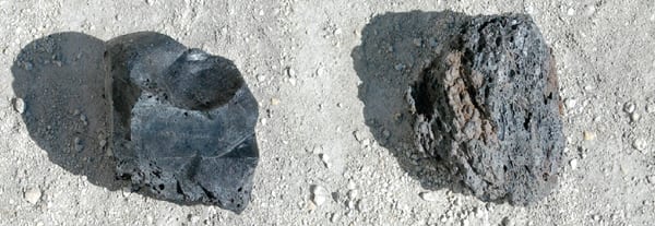 |
| Slag before and after TIFI treatment. Because treated deposits are friable, they are easily removed by sootblowing from the radiant and convective sections of the boiler. Source: Fuel Tech Inc. |
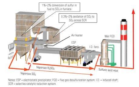
Fuel Tech has worked closely with Santee Cooper to help optimize control of slag, fouling, sulfur trioxide (SO3), and ammonium bisulfate (ABS) at its Cross Station plant near Pineville, S.C. The ultimate goal of this work was to ensure fuel flexibility without having any negative impact on environmental systems. This goal became very important on Units 3 and 4 because the plant planned to burn coal with up to 4.5 pounds (lb) of SO2 per million Btu. High-sulfur fuels, in combination with catalyst SO2 to SO3 conversion rates of 1.0%, lead to significant increases in SO3 generation and ABS formation.
In April 2006, Fuel Tech began a catalyst reagent program, its trademarked Targeted In-Furnace Injection (TIFI), that was very successful at controlling SO3-related opacity and furnace slag and fouling, as well as preventing large-particle ash (LPA) formation and selective catalytic reduction (SCR) fouling. In 2008, Fuel Tech’s SCR Consulting Services group became involved to help optimize catalyst life and lower operation and maintenance (O&M) costs by developing modeling injection strategies to improve overall SO3 and ABS control. An additional benefit was that Santee Cooper was able to run one unit an additional 8,000 hours on a catalyst that had been recommended for replacement a year earlier.
The Basics of SCR Operation
SCR is the most efficient post-combustion NOx reduction technology and entails the injection of ammonia (NH3) into the flue gas downstream of the boiler and reaction with NOx upon a catalytic substrate at temperatures generally within the range of 550F to 750F. NOx reduction efficiencies as high as 95% have been achieved in the most favorable cases.
In general, the following reactions are responsible for NOx reduction:
2NH3 + 2NO + ½O2 → 3H2O + 2N2
4NH3 + 2NO2 + O2 → 6H2O + 3N2
SCR functionality is challenged by chemical and physical processes that can interrupt efficient NOx performance. Chemical deactivation of the catalyst is caused by chemical attack on the active sites of the catalyst, and small-scale plugging of catalyst micropores is caused by the agglomeration of very fine scale ash, aerosols, and condensate. These two types of “poisoning” are diagrammed in Figure 1.
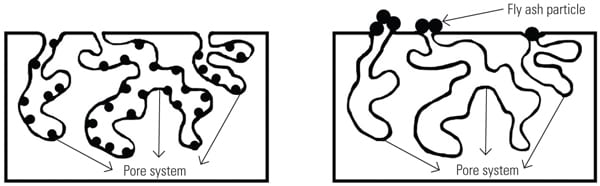 |
| 1. Two pathways to deactivation. An SCR can be deactivated by either chemical attack of catalyst active sites (left) or by physical blinding/plugging of catalyst micropores (right). Source: Fuel Tech Inc. |
Additionally, LPA can completely cover large sections of catalyst sites, preventing even distribution of furnace flow and NOx reduction. Ultimately, this means less catalyst surface area is available for the NOx reduction processes.
Factors That Can Affect SCR Performance
Many factors can affect catalyst performance, including these:
- Fuel characteristics. Many higher-slagging coals have characteristics that are less than ideal due to high slag and fouling characteristics and their potential for increasing catalyst fouling. Chemical poisons such as arsenic present in the coal can permanently reduce the NOx removal efficiency of a catalyst.
- Furnace gas flow distribution. Furnace gas flow distribution can be affected by many factors that create challenges associated with retrofitting SCR systems on older units. Some unit retrofits have less-than-ideal flow distribution, and higher slagging conditions in the furnace and fouling in the convective pass can prevent good furnace gas flow distribution. LPA fouling of the catalyst exacerbates flow distribution problems that affect efficient catalyst performance and NOx removal.
- Ammonia injection grid control system. Poor furnace gas flow distribution and fouling can negatively affect ammonia distribution. This can cause higher levels of ammonia slip and inefficient NOx removal. To overcome these conditions, the ammonia control system increases ammonia injection rates to overcome poor ammonia distribution and facilitate NOx removal. These actions often cause greater levels of ammonia slip, ABS formation, and air preheater (APH) fouling. This is one of the reasons that catalyst is sometimes prematurely replaced—even if a lot activity is still available.
Targeted In-Furnace Injection Technology
The TIFI process was initially designed as a slag and fouling control program that specifically targets areas of the radiant and convection sections of a boiler. Targeting the problem areas of the furnace, instead of simply applying chemical to the fuel, increases performance and cost effectiveness. Recent developments allow the use of TIFI to control SO3 formation and reduce high stack opacity (caused by sulfuric acid) and APH fouling related to these conditions.
In the TIFI process, a treatment reagent is mixed with water and then injected into the flue gas stream. The areas that are targeted are identified by computational fluid dynamics (CFD) modeling to ensure maximum coverage where problem areas are known to exist.
The chemical is added to the flue gas stream to treat problem heat transfer surfaces or at regions where chemical reactions favor SO3 formation. This targeted injection ensures that the chemical reaches the problem areas, ensuring effective utilization. The chemical reacts with slag as it is forming and penetrates existing deposits to affect their crystalline characteristics. In short, the slag deposits are made more friable and therefore are easier to remove.
TIFI technology utilizes multiple CFD models coupled with a proprietary virtual reality–based visualization software system. Advanced visualization brings these simulation methods to life and creates a detailed virtual model of the furnace. Injection overlays and dosage maps are used to predict where the chemical is going and to ensure effective coverage of the targeted zones. The immersive and interactive nature of the simulation enables designers to intuitively discern problems and to improve the process design. Moreover, users can see the visualizations and provide input based on years of experience with operating a unit.
Targeted injection is simulated with proprietary models that evaluate the distribution of the reagent in the flue gas. An interactive injector model enables quick optimization of the needed droplet trajectories and resulting penetration. A rigorous model is then used in the CFD solution to precisely determine the distribution of the chemical treatment. The TIFI injection strategy utilizes a variety of injector designs to provide treatment on the walls, the convective pass, and the inlet to the SCR and APH, as noted in Figure 2.
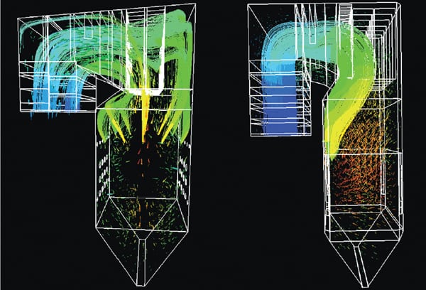 |
| 2. CFD visualizations of droplet trajectories. Note how injection is targeted to ensure proper coverage in the furnace, including the backpass. Source: Fuel Tech Inc. |
The visualization tools are also used to illustrate the likely slag and fouling fronts in the furnace. In Figure 3, the translucent reddish orange iso-surface has been created to visualize a potential ash fusion temperature of 2,150F. The model shows the operators and designers quite clearly where slag and fouling are likely to first occur. When chemical injection is targeted, this unique and powerful approach can control slag and fouling to a degree not possible before.
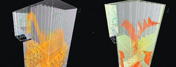 |
| 3. CFD visualization of surface temperatures. Source: Fuel Tech Inc. |
To ensure adequate chemical coverage for both SO3 and ABS control, backend modeling and visualization are performed to ensure adequate chemical concentration and distribution prior to the SCR and APH (Figure 4).
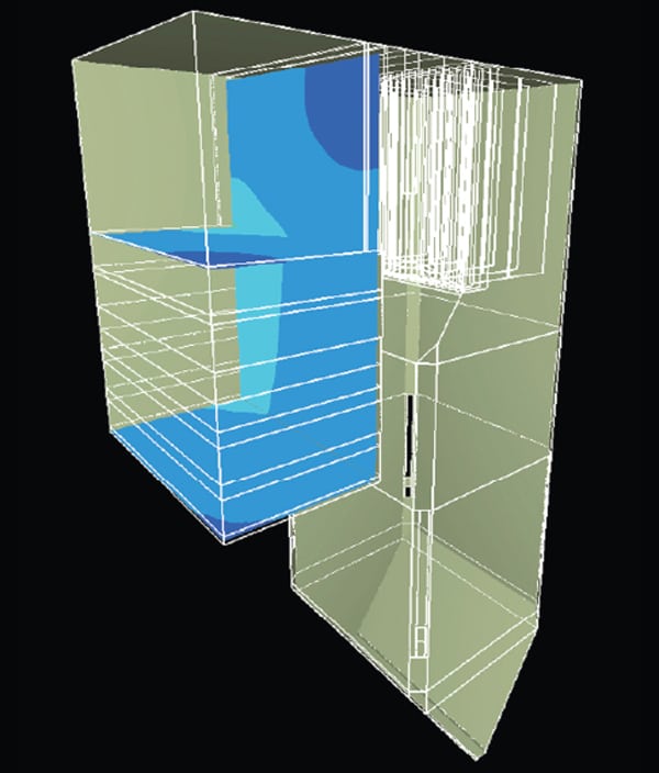 |
| 4. CFD visualization of chemical concentrations. The horizontal planes are color coded for chemical concentration. Light blue indicates the nominal amount of chemical, dark blue to green indicates areas requiring additional chemical, and green indicates areas of excess chemical concentration. Source: Fuel Tech Inc. |
Selecting Reagent Chemistry
The TIFI reagent is a stable chemical slurry with high reactivity due to its high relative surface area. The high activity results in better performance at recommended treatment dosages while its high stability eliminates many of the handling and feeding problems associated with unstabilized compounds.
The chemical reagent arrives at the customer site in the form of suspended slurry of 5- to 8-micron–sized particles. Chemical injection distribution systems, guided by the CFD and injection model results, provide the desired reagent coverage of the walls, the convective pass, and the furnace gases.
In the case of the Cross Station, the TIFI process uses magnesium oxide (MgO) to change slag characteristics and also to mitigate SO3 and ABS formation. Starting as magnesium hydroxide (Mg(OH)2) in the form of a slurry, the chemical travels into the furnace, becomes superheated, and ultimately forms nanometer-size particles of MgO. These very small particles behave almost like a gas and travel with the flue gas stream. This becomes important not only for slag control but also for SO3 and ABS mitigation.
The reagent, enhanced by the rapid heating, quickly begins to interact with the existing deposits and the deposit formation mechanisms through crystal morphology to control the slag accumulation and downstream fouling. This slag control leads to a decrease in SO3 formation. In addition, the gas stream treatment, through acid-base neutralization reactions, reduces much of the SO3 that is formed. Control of the SO3 reduces sulfuric acid and ABS concentrations, APH fouling, and stack opacity issues.
Chemistry of SO3 Formation
The formation of sulfur oxides (SOx) depends on reaction kinetics, combustion temperatures, fuel sulfur content, ash composition, and the level of excess air (O2). Most fuel-bound sulfur oxidizes to SO2 in the combustion zone. The further oxidation of SO2 to SO3 is brought on by three mechanisms:
- Oxidation of SO2 in flame by atomic oxygen: SO2 + O ↔ SO3
- Oxidation of SO2 by molecular oxygen: SO2 + ½O2 ↔ SO3
- Catalytic oxidation via molecular oxygen: 2SO2 + O2 → 2SO3
The third mechanism results in the catalytic conversion of SO2 to SO3. This is primarily due to metal oxides present in the furnace as well as in the catalyst itself. Typical metals include iron and vanadium, which are found in the ash particles, slag deposits, fouled metal heat transfer surfaces, and the SCR.
SO3 in the post-combustion gases will react with the moisture in these gases to form sulfuric acid in the APH:
SO3 + H2O → H2SO4
Once formed, the sulfuric acid condenses on the cold metal surfaces of the APH or downstream equipment. This condensed acid can cause corrosive damage or simply provide a site for ash buildup and eventual APH pluggage that may cause an unplanned outage.
In units equipped with ammonia- or urea-based NOx reduction systems, interaction between residual ammonia and SO3 is an important factor in determining system performance. High concentrations of SO3 prior to the APH will limit the available NOx reduction. This is because residual NH3 reacts with SO3 to produce ABS in the APH at approximately 400F:
NH3 + SO3 + H2O → NH4HSO4
ABS deposits are sticky, difficult to remove, accelerate corrosion, and create significant APH fouling. As the ammonia slip and fuel sulfur concentration increase, the ABS deposition temperature will increase, and the APH pressure drop (dP) will rise. In particular, this becomes more significant when coal has a sulfur content greater than 1.5%.
The Advantages of Using TIFI
Targeting specific chemicals to specific regions on the steam generator allows the operator to directly manage the troublesome SO3, control ABS, reduce arsenic poisoning of the catalyst, and reduce slag formation.
Improved SO3 and ABS Control. The TIFI reagent treatment strategy controls SO3 formation by both limiting the catalytic opportunities for oxidation and providing a clean and efficient furnace that can function well at lower levels of excess oxygen. In addition, TIFI technologies provide SO3 capture to limit or eliminate the effects of sulfuric acid and ABS impacts downstream at the APH.
Magnesium oxide reacts with SO3 to form magnesium sulfate:
MgO + SO3 → MgSO4
The same environment that causes the formation of sulfuric acid also allows for a classic acid-base reaction between magnesium hydroxide and magnesium oxide with sulfuric acid and ABS:
Mg(OH)2 + H2SO4 → MgSO4 ∙ 2(H2O) MgO + H2SO4 → MgSO4 ∙ H2O
MgO + NH4HSO4 → MgSO4 + NH3+ H2O
Improved Arsenic Control. Arsenic is one of the metals that will significantly degrade catalyst life by poisoning the active site where NOx removal occurs. Once the active site is replaced by arsenic, it is not available for NOx reduction. This permanent poisoning of the catalyst shortens catalyst life and allows more ammonia slip to occur. The diagram in Figure 2 demonstrates the NOx removal process.
The TIFI process has several positive effects on catalyst life and reducing the negative effects of poisons:
- Minimizing slag and fouling reduces LPA formation and improves furnace gas flow distribution prior to the catalyst.
- Magnesium and calcium react directly with gaseous arsenic, minimizing poisoning:
As2O3(g) + 3CaO + O2 → Ca3(AsO4)2(s) As2O3(g) + 3MgO+ O2 → Mg3(AsO4)2(s)
- MgO reacts directly with SO3, and this minimizes the opportunity for calcium to also react with SO3 to form calcium sulfate. As a result, more calcium is made available to tie up gaseous arsenic.
TIFI has several positive effects on arsenic control. Better management of slag, fouling, LPA, SO3, and ABS reduces furnace gas flow imbalances prior to the SCR. Furnace gas flow imbalances from slag, LPA fouling of the catalyst, and APH fouling can change the flow balance to less-than-optimal distribution. Blocked flow paths can concentrate furnace gas flow through smaller cross-sectional areas of the catalyst. Catalyst poisons even in low concentrations can lead to premature shortening of catalyst life in sections of the catalyst.
Reduce Slag Formation. TIFI makes ash more friable in both reducing and oxidizing conditions (see photo at the top of this story). This is because MgO has a melt point of approximately 5,000F. MgO interspersed in slag prevents strong fusion of the inorganic constituents (including iron, calcium, and sodium) typically found in coal and the subsequent ash. With TIFI, performance improves even on units with less-than-optimal combustion. This allows units to successfully burn nondesign fuels that have lower fusion temperatures. Ultimately, TIFI provides greater fuel flexibility on many different types of units.
Cross Station Case Study
TIFI has been used on Units 1, 2, 3, and 4 at Santee Cooper’s Cross Station since first introduced in 2006. The following summarizes the plant’s experience with TIFI on Units 1, 3, and 4, by unit.
Cross Station Unit 1. Santee Cooper’s Cross Station Unit 1 is a 600-MW opposed wall–fired unit that began commercial operation in January 1995. It was equipped with staged combustion low-NOx burners. The unit had issues with large particle ash (also known as “popcorn ash”) formation from the start of initial operation.
The unit also had issues with tube thinning in areas of the furnace adjacent to the burners due to reducing conditions in that area, as well as persistent problems with burner eyebrows, burner fires, furnace imbalance, and APH pluggage (which was attributed to LPA). An SCR was added to Unit 1 in 2003.
Subsequently, LPA also blinded the SCR and protective screens. Year-round SCR operation began in June 2004. In April 2006, Fuel Tech began a TIFI program that was very successful at controlling SO3 and furnace slag and fouling, as well as preventing LPA formation and SCR fouling. Figure 5 shows the improvement in performance achieved as a result of these system changes in 2008. The fuel used by this unit has up to 3.3 lb SO2 per million Btu and iron as high as 23%.
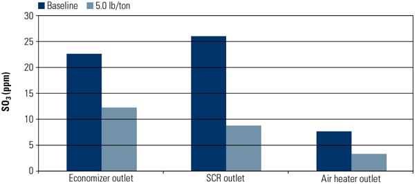 |
| 5. Earlier test results. TIFI modifications completed in 2008 resulted in reduced SO3 production. Source: Fuel Tech Inc. |
The SCR dP was also reduced after the TIFI treatment, which is noted by the yellow vertical line (Figure 6). The numerous cleanings by vacuuming of the catalyst also were no longer required after treatment began. The TIFI program has demonstrated successful LPA control for six years, and there have been no online cleanings or unplanned outages related to SCR performance since April 2006. SCR inspections continue to show the ash to be very friable and without the presence of LPA.
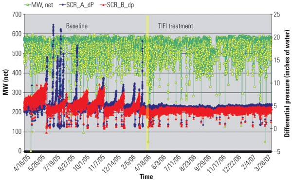 |
| 6. Permanent pressure drop. The SCR dP before and after TIFI treatment is shown by the yellow line. The red and blue lines are the dPs for the A and B duct SCRs. The ash has remained very friable since the installation of TIFI. Source: Fuel Tech Inc. |
In 2005, Unit 1 had ash screens installed to help reduce SCR fouling. Screen integrity was poor, and the ash screen had consistent failures due to erosion. Prior to TIFI, SCR fouling still occurred after screen integrity became compromised. After the TIFI program demonstrated successful control and prevention of LPA, the ash screens were no longer maintained, and they were removed in 2009. After more than five years of operation using TIFI, the catalyst has not experienced high SCR dPs or fouling. Moreover, the unit has operated without any ash screens for over three years. The performance data shown in Figure 7 is with no ash screens installed in the unit.
Figure 7 also shows that Unit 1 enjoyed a very successful run for 19 months, during which TIFI controlled SCR dPs. Moreover, when Unit 1 began exhibiting high ammonia slip between 3 and 15 ppm starting in June 2011, TIFI was able to control formation of ABS, reduce the APH dPs, and prevent the need for an unplanned outage. APH washes were not performed on this unit.
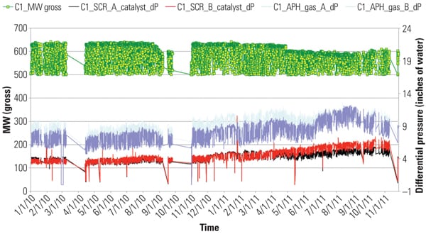 |
| 7. Record run. Unit 1 recorded a 19-month run during which the SCR dP remained under control, even with no LPA screens in place. The black/red lines represent the SCR dPs, and the blue/light blue lines represent the APH dPs. Source: Fuel Tech Inc. |
The catalyst original equipment manufacturer originally recommended replacement of the catalyst in the spring of 2011. Based on the plant’s operating history and the performance data presented above, minor adjustments in TIFI dosage control were recommended to help control ABS. Santee Cooper chose to run with Fuel Tech’s ABS control strategy, and delay the outage.
The new strategy was in effect from June through November 2011. In November 2011, the catalyst was vacuumed for the first time in 19 months to help extend available active surface area. The ABS control strategy was very successful, and Unit 1 was able to run one additional year before catalyst replacement. Ultimately, Cross Unit 1 gained an additional 8,000 hours of catalyst operation without sacrificing NOx performance.
Cross Station Units 3 and 4. Units 3 and 4 are identical tangentially fired units. Unit 3 went into commercial operation in January 2007, and TIFI began in January 2008. TIFI began on Unit 4 in August 2008, and the unit went commercial in October 2008. They were both equipped with two layers of Babcock Hitachi catalyst with an SO2 to SO3 conversion rate of 0.5% per layer. The total conversion rate on startup was 1.0% for two layers, based on a design SCR inlet temperature of 741F. The fuel used by these units has up to 4.5 lb SO2 per million Btu and iron as high as 25%.
However, these units operate above 741F SCR inlet temperatures on a regular basis due to various fuels and operating conditions. With 4.5 lb SO2 per million Btu sulfur in the coal (approximately 1,800 ppm SO2), the catalyst will generate 18 to 30 ppm SO3 at various operating conditions. The conversion of SO2to SO3 at 760F with 3.58% (dry) excess O2 increases by 25%. At 775F and 3.58% (dry) excess O2, an additional 50% more SO3 would be expected. TIFI successfully controlled SO3 and ABS formed under each of these operating conditions.
In February 2008, Unit 3 had various issues with ammonia control that led to excessive ammonia slip and APH fouling. TIFI had been installed in January 2008 with the initial goals of controlling slag, fouling, and SO3-related opacity. The variability in ammonia slip required Fuel Tech to incorporate new control and injection strategies to ensure fuel flexibility and control of APH fouling. ABS control was initially demonstrated in July 2008, and the TIFI program allowed Unit 3 to make it to the October outage. The first successful demonstration of a cleanup of an APH fouled with ABS occurred in September 2008. The successful cleanup led to a 2.5 inches of water pressure drop in the APH (Figure 8). Fuel Tech subsequently performed ammonia testing on Unit 3 and found ammonia slip levels as high as 7 ppm in the “B” duct SCR outlet.
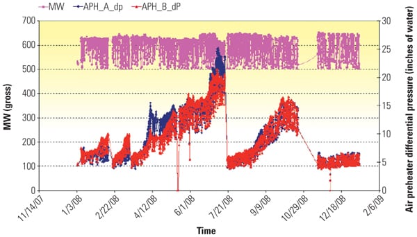 |
| 8. Unit 3 test results. The 2008 tests confirmed that the ABS fouling of the APH was removed and the pressure drop was reduced by 2.5 inches. Source: Fuel Tech Inc. |
During the October 2008 outage, APH wash water samples were collected and analyzed to determine the various foulants present. The analysis confirmed the presence of ABS, and its conversion to magnesium sulfate. The total Mg content in the fuel ash prior to TIFI was less than 1.0%. The water analysis showed high levels of magnesium due to the TIFI process. This analysis and the reduction in APH differential pressures provided proof of ABS conversion to magnesium sulfate. This success led to additional optimization strategies.
In 2009, Unit 4 began experiencing high ammonia slip due to catalyst degradation. High arsenic levels in the coal were found to be one of the key factors. In July 2009, Fuel Tech was tasked to control ABS and help the unit reach the October 2009 outage. With TIFI in operation, the APH cleanup dropped the differential pressures 3.1 inches, as shown in Figure 9.
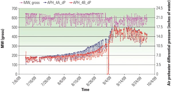 |
| 9. Keep Unit 4 running. TIFI operation on Unit 4 to allowed the unit to operate until its next planned outage. The APH pressure drop was reduced by 3.1 inches. Source: Fuel Tech Inc. |
Later, ammonia slip caused by overfeed of ammonia due to performance problems with the ammonia injection controls caused a rapid rise in APH differential pressures. An online APH cleanup was implemented to reduce differential pressures. The successful APH cleanup resulted in a differential pressure drop of 6 inches while the unit maintained full load. After the APH cleanup, the ammonia control issues were resolved. Unit 4 was able to return to normal control without a need for an APH wash (Figure 10).
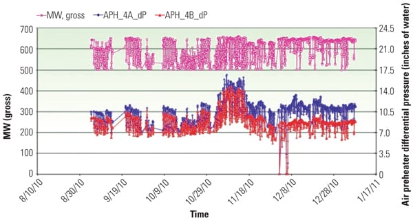 |
| 10. Unit 4 test results. High ammonia slip due to ammonia control issues caused the APH differential pressure to rise rapidly. APH cleanup was performed at full load, and differential pressure dropped 6 inches. Source: Fuel Tech Inc. |
The Bottom Line
Optimizing catalyst life and lowering O&M costs is possible. However, using high-sulfur and high-slagging coals makes extending SCR catalyst life a significant challenge. Fuel Tech’s TIFI program has proven that by successfully controlling slag, fouling, SO3, and ABS (even when ammonia slip reaches 15 ppm) catalyst life can be extended, providing operational flexibility, even when burning very difficult fuels.
— Michael B. Davis, PE (mike.davis@santeecooper.com) is a plant manager for Santee Cooper. Volker Rummenhohl (vrummenhohl@ftek.com) is vice president, catalyst technologies, Howard Benisvy (hbenisvy@ftek.com) is regional sales manager, and Kent W. Schulz (kschulz@ftek.com) is market development manager for Fuel Tech Inc.