All turbo machinery is subject to degradation that, over time, will affect the system’s efficiency and operational performance. Precise monitoring of turbo machinery performance with continuous torque-monitoring systems can be used to identify gradual efficiency loss. That, in turn, allows a more focused maintenance scope to be developed that can return the system to its optimum operation and efficiency.
Torque monitoring based on heat balance, energy balance, and other methods requires measuring numerous parameters such as pressure, temperature, flow rate, and gas composition, which require high-accuracy instrumentation. However, phase displacement technology can be used to accurately measure torque directly at the coupling to within 1% of full-scale torque, a combination of all electrical and mechanical sources of error.
Measure the Torque
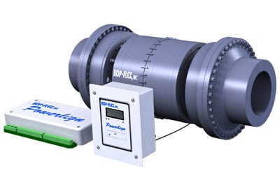
A torque-monitoring system was recently installed on a cracked-gas compressor train at Qenos Olefins in Australia to determine the causes of a power limitation. The Kop-Flex Powerlign system installed utilizes phase displacement technology for long-term reliability, eliminating the need for recalibration.
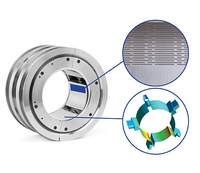
Two rings with pickup teeth are installed on a torsionally soft spacer and are intermeshed at a central location. Two monopole sensors 180 degrees apart are mounted on the coupling guard. As the coupling rotates, the ferromagnetic teeth create an AC voltage waveform in the sensor coil, which is digitally processed using known calibration parameters. Because of the intermeshed pickup teeth, the system is referred to as a single-channel phase displacement system, producing two independent torque measurements (Figure 2). The Powerlign system will output torque, power, speed, and temperature, which can be easily integrated with any distributed control system (Figure 3).

@font-face {
font-family: “Times”;
}@font-face {
font-family: “Cambria”;
}p.MsoNormal, li.MsoNormal, div.MsoNormal { margin: 0in 0in 0.0001pt; font-size: 12pt; font-family: “Times New Roman”; }div.Section1 { page: Section1; }2. Tracking two signals. The Powerlign system produces two independent torque signals. Source: Kop-Flex
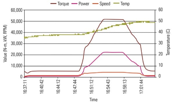
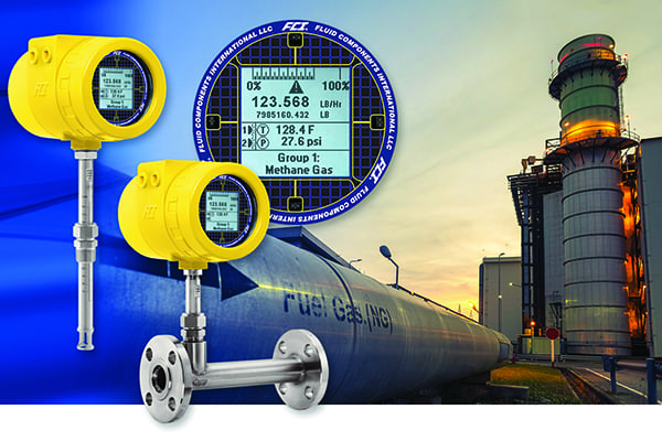
3. Important stats. Typical output from the Powerlign system includes torque, power, speed, and temperature. Source: Kop-Flex
At the Olefins plant the operating cycle of the steam-driven, cracked-gas compressor train is seven to eight years. During this cycle the plant eventually has production limitations because the compressor train encounters a power limit. “Turbine fouling” or “compressor fouling” or a combination of both caused the power limit. The true cause had long been the subject of an engineering debate among the Machinery group, Process Engineering group, and Operations department.
The power loss was so important that the plant considered upgrading the turbine’s power rating from 7.5 MW to 9 MW. This upgrade would have required a capital investment of $2 million, so the plant elected to defer this investment and instead installed a torque meter during the last eight-year major overhaul shutdown.
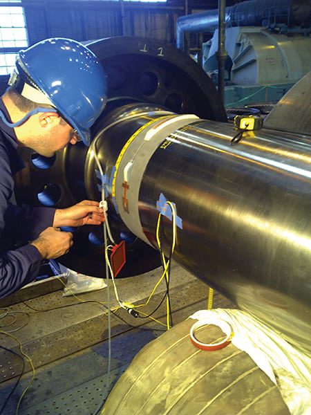
The installation involved replacing the existing coupling spacer and flexible halves with a “drop-in” torque meter and integral flexible elements (Figure 4). The torque meter assembly was dynamically balanced to API standards so it was not necessary for the user to return any coupling components for the retrofit. The coupling guard was modified so that the two variable-reluctance sensors could be installed, completing the mechanical installation (Figures 5 and 6).
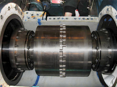
5. Shaft replacement. The original shaft spacer was replaced with a Smart Spacer. Courtesy: Kop-Flex
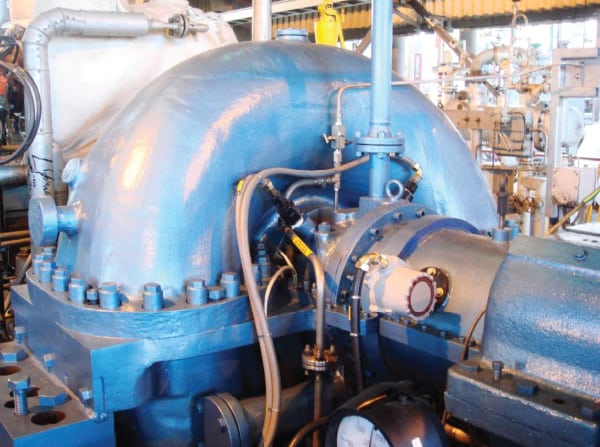
6. Back in business. This is the completed mechanical installation of the Powerlign system. The spacer is covered with the shaft shield. Courtesy: Kop-Flex
Successful Restart
The plant was restarted after completing a number of compressor efficiency improvements during the overhaul outage. The data collected from the torque meter clearly showed the 7.5-MW steam turbine did not require an uprate and that the major power losses were coming from the compressor. The torque meter also allowed online tuning of the seal gas system of the compressor to establish the lowest power draw. The turbine load was reduced an additional 200 kW with the manual adjustments made on the seal gas system alone.
The torque meter is now being used to monitor turbine steam fouling issues and processes related to compressor fouling so that the corrective online washing can be activated as soon as performance is affected.
The historical data collected from the torque meter will also provide a baseline of mechanical loading through the drive drain of the cracked-gas compressor over time. This data will be used to determine if increases in the maximum continuous operating speed rating of the compressor and the turbine can be accomplished at minimal cost. If so, this will increase the operating envelope of the compressor.
The value of the torque meter justified installation of a second system in the plant’s second steam cracking plant turbine/compressor train in October 2012.
—Contributed by Daniel Phillips (daniel.phillips@emerson.com), manager, field service engineering, Kop-Flex, Emerson Industrial Automation; Trevor Mayne (trevor.mayne@qenos.com), machinery engineer, and Mark Ellul (mark.ellul@qenos.com), an I & E specialist, for Qenos Olefins Pty Ltd, Australia.