Turbine water induction protection systems are designed to keep water out of the turbine and prevent damage. Steam turbine damage from water induction is a costly economic, safety, and reliability concern. Any connection to the turbine is a potential source of water, either by induction from external equipment, or by accumulation of condensed steam.
The American Society of Mechanical Engineers (ASME) formed a committee to address this issue, and the first standard for induction protection, TDP-1, was issued in 1972. The standard has been revised several times, with the latest revision in 2013, which was made mandatory for new installations.
The standard is applicable to conventional steam cycle, combined cycle, and cogeneration plants. It covers design, operation, inspection, testing, and maintenance to prevent induction from: motive steam systems, steam attemperation systems, turbine extraction/admission, feedwater heaters, turbine drains, turbine steam seal systems, startup systems, condenser steam and water dumps, and steam generator sources. A typical drain pot and instrument system is shown in Figure 1.
![Fig 1 Typical Drip Leg[1].wmf](https://www.powermag.com/wp-content/uploads/2018/02/fig-1-typical-drip-leg.jpg) |
| 1. Drain pot and instrument system. The American Society of Mechanical Engineers (ASME) issued its first standard for induction protection, TDP-1, in 1972, and has since revised it numerous times, with the latest revision in 2013. This diagram shows a typical drain pot and instrument system with redundant level elements, based on ASME’s TDP-1. Courtesy: Fossil Power Systems (FPS) |
Turbine Water Induction Protection (TWIP) Requirements
The ASME’s TDP-1, “Prevention of Water Damage to Steam Turbines Used for Electric Power Generation: Fossil-Fuel Plants,” issued in 2013 states that if a steam plant equipment malfunction should occur, the TWIP system should:
■ Detect the presence of water before water has caused damage.
■ Isolate the water by manual or, preferably, automatic means.
■ Dispose of the water by manual or, preferably, automatic means after it has been detected.
Additionally, “No single failure of equipment, device, or signal, or loss of electrical power, shall result in water or cold steam entering the turbine.”
An electric power utility in the southeastern U.S. was experiencing reliability problems with the mixture of turbine water induction protection instruments installed at its various facilities. One of its plants sustained costly turbine damage due to protection system failure.
Fossil Power Systems (FPS) was contacted by several individual power plants within this electric power utility, as plant operators were searching for solutions for their malfunctioning TWIP instruments. A corporate engineering team was assembled. The purpose was to evaluate the reported failures of turbine water protection instruments at the various power plants and develop a standard instrumentation configuration that could be implemented at all facilities. The power plant types ranged from older coal-fired units to newer combined cycle plants.
The plants had a variety of TWIP instruments (Figure 2), including original equipment and technologies that had been retrofitted: differential pressure (DP) transmitters, float switches, guided wave radar systems, magnetic-type float gauges, and nuclear level transmitters. Because damage had recently occurred to the turbine at one plant due to water ingress, corporate engineering gave this project a high priority.
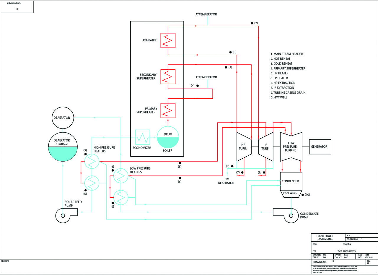 |
| 2. Turbine water induction protection (TWIP) instrument locations. This diagram shows the typical instrument locations in a TWIP system at a power plant. The facilities worked on by FPS had a variety of TWIP instruments, including both original and replacement equipment. Courtesy: FPS |
Process and Application Requirements
Although the process design parameters varied at each plant, they were typical for TWIP systems:
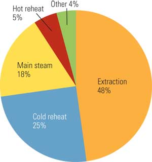
■ Cold reheat: 800 psi at 700F
■ 6th stage extraction: 800 psi at 700F
■ 12th stage extraction: 300 psi at 700F
■ Hot reheat: 800 psi at 1,100F
■ 9th stage extraction: 500 psi at 900F
The water conductivity was nominally 1 to 5 microsiemens. Since these were retrofit installations, a single 4–20 mA signal output was required to utilize the existing wire pair to the control room distributed control system (DCS). In addition, the instrument needed to have self-diagnostics, fault indication, and also be fail-safe to open the automatic drain valve.
The corporate engineering team collected data from the power plants on the various instruments that had been in operation in their facilities. The characteristics of these available technologies were then evaluated and compared to the requirements.
The selections were narrowed to two technologies for this application: conductivity probe instruments and guided wave radar devices. Based on instrument features and performance history, FPS Aquarian conductivity probe instruments were selected for the first full plant retrofit trial.
Probe Column Configurations
Several probe column configurations were considered. Two probe columns are the most typical for this application. However, the corporate engineering team preferred additional level points that would provide more indication and control options. The system’s historical performance could then also be evaluated to detect drain system problems, such as insufficient valve capacity, under all plant conditions.
The four probe AQ1000P electronics and column were selected. A 4–20 mA module was used to convert the probe point level detection to a single 4–20 mA output with the following level functions:
■ Probe 4: Hi-Hi alarm, 19.7 mA signal.
■ Probe 3: Hi alarm, 16.0 mA signal.
■ Probe 2: Open drain valve (controlled by DCS), 12.0 mA signal.
■ Probe 1: Low indication, close drain valve (controlled by DCS), 8.0 mA signal.
■ No water: 4.3 mA signal.
■ Fault: 0.0 mA signal.
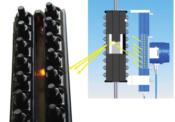
In order to provide system fault analysis, the 4–20 mA level output signal was wired in series with the “level fault” relay (water over steam condition, incorrect level sequence) and the “electronics fault” relay (broken probe wire, loss of AC power, electronics circuit card failure). With this arrangement, fault conditions would be easily identified within the DCS if the 4–20 mA signal dropped to zero (Figure 3).
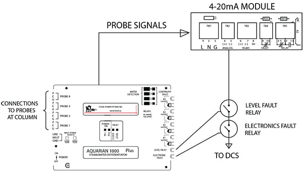 |
| 3. Identifying fault conditions. This diagram shows the AQ1000P electronics 4–20 mA output signal. In this configuration, fault conditions can be identified within the distributed control system if the 4–20 mA signal drops to zero. Courtesy: FPS |
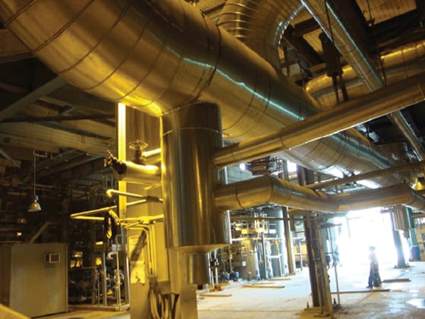
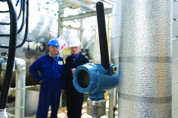
A total of eight FPS Aquarian AQ1000P conductivity probe instrument systems were installed at one facility. A typical installation arrangement is shown in the Figure 4 diagram (a typical drain pot and instrument arrangement), and Figure 5 photo (a typical TWIP system installation). Performance of these systems met all requirements and additional retrofits were authorized. These additional retrofits were coordinated to coincide with scheduled plant outages.
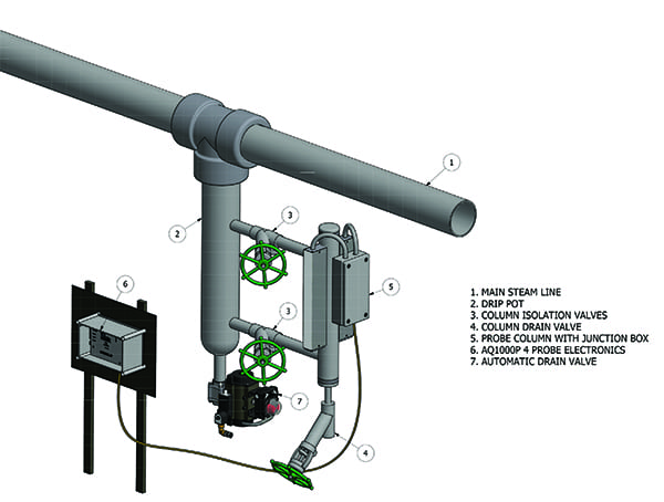 |
| 4. Typical drain pot and instrument arrangement. This diagram shows the arrangement with the drain (drip) pot below the main steam line, with locations of drain valves and other equipment identified. Note the location of the AQ1000P probe electronics. Courtesy: FPS |
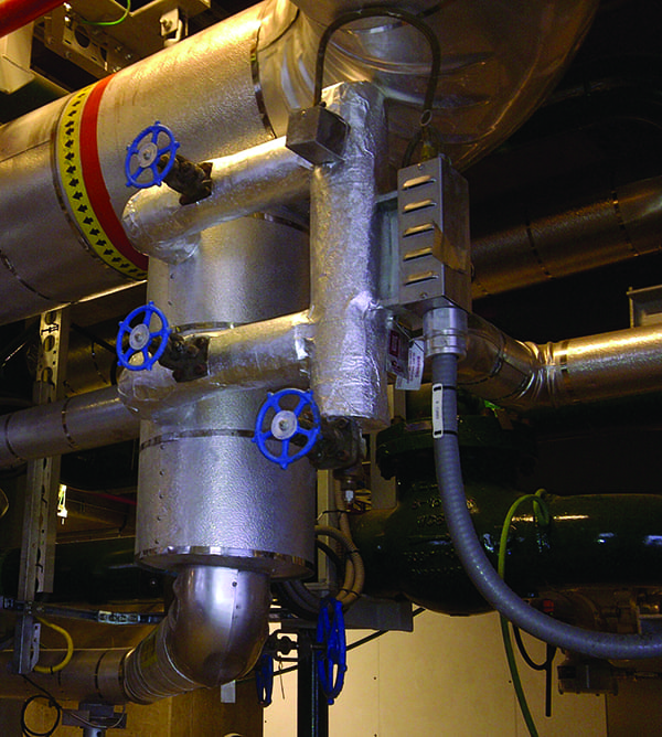 |
| 5. A TWIP system installation. This photo shows a TWIP system installed at a power plant, with valves and drains clearly visible. Courtesy: FPS |
A total of 169 replacement instruments have been installed over a five-year period. Protection and reliability have been restored to power plants at 11 locations, and additional upgrades are planned. The FPS Aquarian conductivity probe instruments has proven to be a suitable technology choice for this TWIP application. The instruments have several attributes, including:
■ No moving parts.
■ Ability to withstand high process temperatures and pressures, and are not damaged by water hammer or influenced by rapid process changes.
■ Are compact for tight spaces and do not require calibration.
■ Detect water in both saturated steam and superheated steam conditions.
■ Provide fail-safe protection and can detect low-conductivity water.
■ Each probe provides an independent signal, and can be tested and serviced while the plant is operating or offline.
■ Are low maintenance under clean superheated steam process conditions.
■ Modifications can normally be made using existing plant drip legs and process instrument connections.
■ Carbon steel and chrome moly piping materials are available to satisfy process design conditions.
■ Meet ASME TDP-1 requirements for TWIP protection.
A properly functioning TWIP system is important to defend against turbine water induction events in steam turbines, with the ability to monitor, detect, isolate, and dispose of errant water critical components to prevent damage.
—David Kalix, PE is level products engineering manager for Fossil Power Systems.