The 1,768-MW Baldwin Energy Complex in Illinois was the site of a joint-venture pilot project to demonstrate a wireless vibration-monitoring system for a coal pulverizer. The partners in the project were EPRI and the plant’s owner, Houston-based Dynegy Midwest Generation.
A key objective of the project was to identify a reliable wireless system capable of providing overall vibration magnitudes at 1-minute intervals to Dynegy’s plant information (PI) historian from OSIsoft Inc. (San Leandro, Calif.). Eventually, the data collected by the PI historian would be routed to control-room displays to provide operators with vibration data values as well as alarm indications. A wireless solution was preferred because it would eliminate the costs of installing conventional Ethernet or fiberoptic cables.
Dynegy has traditionally taken a proactive approach to monitoring vibration levels on mission-critical assets, including such measures as early detection and notification of abnormal machine conditions. The ultimate goal of the pilot project was to enhance equipment reliability and the safety of personnel.
A previously installed wireless pilot system failed to deliver reliable data and was taken out of service after six months. However, Dynegy still considered wireless the way to go. The company decided to evaluate the wireless vibration monitoring systems of two vendors by employing them side-by-side, with each system monitoring different sections of the pulverizer.
Tough environment
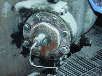
The pulverizer chosen for the vibration-monitoring project is a CE Raymond model 923 equipped with eight Wilcoxon 786A accelerometers (Figure 3). For the evaluation project, additional accelerometers were mounted on two motor sleeve bearings, two worm screw rolling element bearings, another bearing (at the bottom of the bull gear vertical shaft), every grinding roll, and three grinding roll journal assemblies.
|
3. Shake, rattle, and roll. An accelerometer mounted on a grinding roll journal assembly. Courtesy: SKF USA Inc.
|
One reason this particular pulverizer (one of six in the basement of Unit 3) was chosen was its location. The nearest wireless access point is 200 ft away, challenging the range of the competing solutions. Although 200 ft is an acceptable range in office environments, reception over that distance can be spotty in industrial environments where walls, I-beams, pipes, and other metal structures may block or attenuate signals. In the basement of Unit 3, the signals going to and from the wireless system faced many obstacles, including six 5-ft x 5-ft metal air ducts connected to the pulverizers. The typical range of the wireless devices used is 500 to 1,500 ft indoors. Outside, they can cover up to 16 miles, with high-gain antennas.
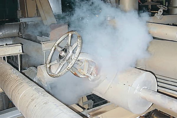
The ambient environment of the pilot was as challenging as obstacles to signals. Down in the basement, temperatures range from 40F to 100F, and flyash and water from wash-downs are abundant. Some monitoring points looked at equipment running at between 45 rpm and 600 rpm (Figure 4).
|
4. What to measure. Initial measurements were used to determine the most effective types of machine condition transmitters for this application. Courtesy: SKF USA Inc.
|
During the pilot period, half of the accelerometers were connected to a wireless vibration monitoring system from the San Diego-based SKF Reliability Systems division of SKF USA Inc.; the others were linked to a system from another vendor. Working from the sensors up, the test of the SKF system began by checking its ability to receive velocity and acceleration readings sent by machine condition transmitters (MCTs). The MCTs delivered general indicators of machine health like levels of imbalance and misalignment, but they also supplied specific variables such as enveloped acceleration (gE), a proxy for bearing degradation.
Although only eight accelerometers were employed, 10 MCTs were used. Two were doubled up, that is, the buffered output from one channel (the raw acceleration signal) served as the input to another in two separate situations. This daisy-chaining of MCTs allowed additional multiparameter measurements to be made without necessitating the installation of more sensors.
All of the MCTs measuring velocity were configured for a 1-inch-per-second (ips) full-scale range; those measuring enveloped vibration were configured for a full-scale range of 10 gE. The MCTs’ 4- to 20-mA processed output was considered representative of the overall channel value. With the help of a 16-channel analog-to-digital converter, the 4- to 20-mA signals were converted to ModBus Ethernet (RS-485) format and sent wirelessly to the access point.
The wireless transceiver selected for the project was a Locus OS2400-485 industrial Ethernet radio from ProSoft Technology Inc. (Bakersfield, Calif.). All of the devices were DIN-rail mounted and fitted into a small, easy-to-mount enclosure. The system was installed and made fully operational in one day.
A failure tests the system
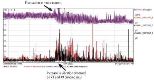
Five days after installation of the SKF system, the pulverizer experienced a failure of the bearing of its #2 grinding roll. The wireless vibration monitoring system was instrumental in notifying plant personnel that a change in the operating characteristics of the pulverizer had occurred. A review of the PI historian showed correlations between changes in pulverizer motor current and vibration trends on the inboard motor bearing, outboard worm shaft bearing, and the #1 and #3 grinding rolls. This prompted Unit 3’s predictive maintenance (PM) engineer to take more in-depth vibration data with a portable analyzer.
Motor current also was plotted along with vibration data from the #1 and #3 grinding rolls. Even though the failure was in roll #2, vibration from the failed roll was strong enough in adjacent rolls for the MCTs to detect it (Figure 5).

|
5. Good results. The correlations between motor current and bearing-related vibration data (top) and between motor current and grinding-roll vibration data (bottom). Courtesy: SKF USA Inc.
|
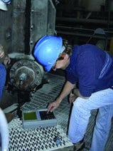
The vibration data collected by the PM engineer, and data collected during an unsuccessful attempt to adjust the grinding roll, prompted project leaders to call for a visual inspection. It confirmed that the #2 grinding roll’s bearing had failed and that the roll had dropped into the bottom part of the grinder and come into contact with the cone assembly.
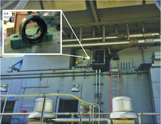
Actually, both of the roll’s bearings had failed and disintegrated. Given the rapidity of the failure, lack of oil in the journal was considered the probable cause. The journal shaft was distorted by heat, and the inner races of the bearing were stuck to the shaft. Furthermore, the bolts holding the upper journal housing to the grinding roll were found to be sheared off. This shearing caused the grinding roll to slide and hit the center-feed pipe, breaking a piece out of it (Figure 6).
|
6. Jelly roll. The pulverizer bearing information was detected too late to prevent a failure. Courtesy: SKF USA Inc.
|

The measurements taken from grinding roll #2 and further analysis confirmed that the MCT system had detected a high vibration level. If the system had been monitoring this particular channel, it is believed that the gE readings would have indicated the fault and shown the vibration spike early enough to prevent a catastrophic failure. After eight weeks of tests, Dynegy chose SKF’s Wireless MCT-System as the winner of the wireless vibration monitoring competition.