Owner/operator: Seminole Electric Cooperative Inc.
Complying with a corporate environmental policy requires much more than just writing a check for equipment upgrades. It takes a dedicated and knowledgeable staff that’s willing to invest years of work to permanently reduce a plant’s environmental footprint. The staff of Seminole Generating Station have completed multiple, incremental plant improvements over the past decade that have significantly reduced air emissions and minimized solid waste disposal.
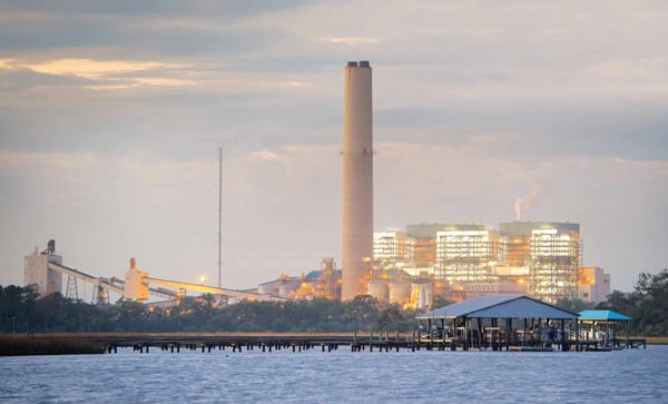
Seminole Electric Cooperative Inc. (SECI) provides electricity to its 10 member cooperatives serving 46 central and northwestern Florida counties. Formed in 1948, SECI was a "paper generation and transmission (G&T) co-op" until the Seminole Generating Station (SGS) was commissioned in January 1984; Unit 2 entered service on December 31, 1984 (Figure 1). SECI is in the process of securing the necessary regulatory approvals for a third unit at SGS. The new plant is to be approximately 750 MW and will use supercritical boiler technology. A final construction schedule has not been determined.
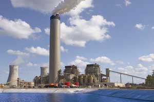
1. A key Florida landmark. Seminole Generating Station consists of two 650-MW steam units that together burn about 11,000 tons of coal daily. Emissions from each unit have been reduced by incrementally upgrading the scrubber, adding low-NOx burners and other combustion system upgrades, and, most recently, adding a selective catalytic reduction system. Synthetic gypsum from the SO2 scrubber is sold to an adjacent wallboard manufacturer. The common stack in the foreground is 695 feet tall. Courtesy: Seminole Electric Cooperative Inc.
SECI is the third-largest G&T in the U.S. based on wholesale energy sales. It owns the two 650-MW coal-fired units at SGS; the Richard J. Midulla Station, consisting of a 500-MW natural gas – fired combined-cycle plant placed into service in January 2002; 310 MW of gas turbine peaking units added in December 2006; and a 15-MW share of Progress Energy Florida’s Crystal River Unit 3 nuclear plant. A combination of long-term capacity and energy purchase agreements from utility and merchant plants, firm renewable capacity, and energy purchase agreements and interchange agreements with 23 other electric utilities completes SECI’s electricity resource mix. SECI produces approximately 43% of its members’ electricity requirements and purchases the remainder.
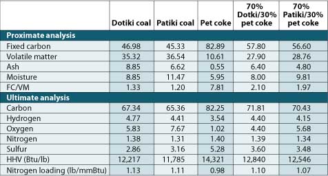
The SGS is located on a 2,000-acre parcel of land 6 miles north of Palatka, Fla., along the St. Johns River. Together, the sister units burn a total of 11,000 tons of washed, 3% sulfur coal each day. Most of the coal is purchased from mines in southern Illinois and western Kentucky. The plant is configured to burn up to 30% petroleum coke blended with coal when the price is right.
Most utilities have an environmental policy that requires them to be proactive in their environmental stewardship, and SECI walks the talk of its corporate environmental policy. It does so by making solid investments in SGS plant operations over many years that go beyond merely meeting minimum regulatory requirements. SECI has been successful in reducing its environmental footprint by preventing "pollution through the minimization, reuse, recycling, and reclamation of materials and products used in our operations," as the company’s environmental policy says. The staff of SGS have proven that a good corporate environmental policy backed by corporate leadership and investment will produce a plant with a superior environmental performance track record. Here’s how they did it.
Recycle the Gypsum
The original plan for the plant’s air quality control system included a "limestone inhibited" wet flue gas desulfurization system designed to remove 90% of the SO2 from the plant’s flue gas. This unoxidized limestone scrubber produced about three-quarters of a million tons per year of a very heavy sludge that was difficult to dewater. Once dewatered, the sludge was blended with fly ash and lime to produce a poor-quality concrete that was stored at an onsite landfill.
In 2000, SGS upgraded its scrubbers to a limestone forced oxidation process at a cost of about $15 million. A mixture of water and 12% limestone is sprayed in the flue gas as it passes through the scrubber, and the SO2 reacts with the calcium in the limestone to produce calcium sulfate, also known as synthetic gypsum. Each unit uses up to 24 tons of limestone per hour. The forced-oxidized system incorporates air injection to ensure a fully oxidized gypsum product. The "synthetic gypsum" produced by the scrubber is readily dewatered to less than 10% moisture before it is ready for recycling into a gypsum-based product.
Lafarge North America Inc., a world leader in building materials, operates more than 2,100 industrial sites around the world. In 1982 the company became the leading cement producer in the U.S. after purchasing General Portland Cement; several other large acquisitions followed in the 1990s. Lafarge opened its second state-of-the-art drywall manufacturing plant in 2001 adjacent to SGS. The generating station soon began deliveries by conveyor of the roughly 550,000 tons per year of synthetic gypsum. Lafarge uses the synthetic gypsum to produce about 900 million square feet of wallboard each year.
The net benefit to SECI (including gypsum sale revenue and reduced costs for landfill operations) is estimated to be $5 million to $6 million a year over the gypsum sales contract term. SECI was the recipient of a Leadership Award from the Council for Sustainable Florida in recognition of the success of this project.
Upgrade the Scrubber
With SO2 allowances selling at historic lows, many utilities may find it more economical to purchase additional allowances required under the Environmental Protection Agency’s (EPA’s) acid rain program. Prices for SO2 allowances have fallen from a 2008 average of $380/ton to less than $70/ton in 2009, a drop of more than 80%. One explanation is the uncertainty surrounding the EPA’s Clean Air Interstate Rule (CAIR), which was issued, challenged, struck down, vacated, and then temporarily reinstated. The unresolved final fate of CAIR has also caused many utilities to pause and wait for the return of more regulatory certainty before committing hundreds of millions of dollars to emission upgrades and retrofits; SECI elected to continue its air emissions projects without delay.
SGS has completed scrubber upgrades to improve the mechanical efficiency of its scrubber operation. "We chose the upgrade-and-additional-controls route instead of purchasing clean air allowances," explains Director of Plant Operations Brenda Atkins. "By upgrading our scrubbers from 90% to 94% SO2 removal, we will also increase our synthetic gypsum production by approximately 75,000 tons each year."
Another side benefit is the additional and very valuable allowances earned before the EPA’s 2010 deadline for receiving full credit of banked allowances.
The upgraded process is also capable of using an organic dibasic additive (DBA) to improve scrubbing efficiency to 98%, but the cost of the chemicals and other downstream water treatment difficulties make it an unattractive alternative at present.
Add New Low-NOx Burners
Each SGS unit features opposed wall-fired Foster Wheeler (FW) boilers designed for 4,700,000 lb/hr MCR at 1,005F/1,005F main and reheat steam conditions. The design of each steam generator included moderately high burner zone heat release rates that are known to have a higher potential for NOx formation. In 1986, FW retrofitted an overfire air (OFA) system on the front and rear walls of both boilers.
In the fall of 2006, FW replaced the existing controlled-flow split-flame burners on SGS Unit 1 with new VS low-NOx burners to further reduce NOx emissions. In addition, the OFA system was upgraded with new FW VS OFA registers to provide increased OFA flow and better mixing. These same modifications were made to Unit 2 during the spring of 2007. New OFA throats and registers were installed at the same elevation above the outboard burner columns on both the front and rear walls. Baffle and turning vanes were added inside the windboxes to better distribute incoming secondary airflow to the burners and OFA system.
The OFA system upgrade resulted in an increase in OFA flow from approximately 10% to 25% of the total combustion air used to further reduce NOx formation in the upper portion of the combustion zone.
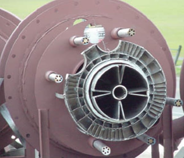
Unit 1 coal balancing was performed by adjusting the FW riffles installed at both outlets of each ball mill that are checked by an FW ECT coal flow measurement system. Each assembly has the capability of diverting coal flow between the three outlet coal pipes at each end of the ball mill as well as some side-to-side distribution control (Figure 2).

2. Continuous balancing act. An adjustable riffle assembly was installed on the 12 total mills used in Seminole’s two units to balance the air-fuel pipe flows to the upgraded low-NOx burners and overfire air systems. Courtesy: Foster Wheeler
Baseline testing was performed on Unit 1 during January 2006 with a blend of 70% Patiki coal and 30% pet coke prior to the combustion upgrades. Pre-retrofit NOx emissions were 0.53 lb/mmBtu at a load of 700 MW with all mills in service and the top feedwater heater out of service. Post-retrofit NOx emissions collected during a performance test conducted in March 2007 were below 0.35 lb/mmBtu for a blend of 70% Patiki coal and 30% pet coke. This corresponds to a reduction in NOx of approximately 35%. Unit 2 was retrofitted with the new low-NOx system in April 2007 and began start-up in May 2007 with comparable NOx reduction numbers.
CO emissions of less than 175 ppm were attained over the load range during performance testing. The CO emission target of 200 ppm was easily met with a blend of 70% Patiki coal and 30% pet coke and was well below the baseline prior to the retrofit (125 ppm versus 167 ppm). The low CO emissions can be attributed to fine control of the secondary air and good jet penetration and mixing of the OFA with the combustion gases rising from the burner zone.
Add a New SCR to Further Reduce NOx
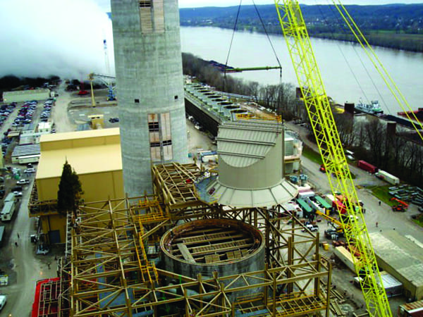
In 2006, Hitachi Power Systems America Ltd. (Hitachi) was awarded an engineering, procurement, and construction contract by SECI for a selective catalytic reduction (SCR) system retrofit on both SGS units (Figure 3).

3. Latest air emissions reduction upgrade. Hitachi designed and installed selective catalytic reduction (SCR) systems on both units at SGS. Post-installation testing showed the SCRs exceeded the 90% contract guaranteed NOx removal rate. Courtesy: Hitachi Power Systems America Ltd.
Hitachi’s contract included the design, supply, and erection of the SCR systems to achieve 90% NOx reduction. This goal was achieved through the integration of Hitachi’s process system design with Hitachi’s low SO2 -oxidation, plate-type catalyst. The SCR system also includes:
-
An ammonia injection grid/static mixing system to promote thorough mixing of ammonia and NOx prior to entering the SCR.
-
Hitachi’s patented reactor hood design.
-
A complete air preheater rebuild and induced-draft (ID) fan replacement, including foundation rework.
Ammonia required for the SCR systems is produced on site by a urea-to-ammonia system in which a urea solution is converted to gaseous ammonia. This system safely avoids the onsite storage and handling of ammonia. SECI believed that investing about $25 million in this system would return a "good neighbor" dividend in the form of increased safety.
Integration of the new SCR system with the existing boiler was handled in two phases for each of the two SCR projects. Phase 1, scheduled for a 30-day outage, included installation of the new economizer outlet flues, SCR diverter dampers, and partial replacement of the air heater inlet flues. Temporary blanking plates were installed at the SCR inlet and outlet connections, allowing the unit to safely operate at the conclusion of this phase and making installation of the entire SCR possible prior to Phase 2. Phase 2 included upgrading the air heater rotors, installing the underground utilities, modification of the ID fan concrete foundations, replacement of four ID fans, and commissioning.
The four ID fans, each rated at about 33% of full-load capacity, were replaced because of the pressure drop that SCR added to the gas path. The choreography associated with this upgrade was well planned months in advance.
The upfront fan foundation work started shortly after completion of the first phase and was completed prior to start of the second phase. This initial work included installation of the dowels and rebar in and around the existing motor and fan pedestals. As this work was performed with all fans in service, the bearing vibration levels had to be monitored closely by the operators. Twelve days prior to beginning the second outage, the first fan was taken out of service and the primary fan work started. The existing fan was demolished, modification of the foundation was completed, and the new fan was installed.
Two additional fans were removed from service at the start of the outage and the same process was repeated. The fourth fan remained in service for the initial two days of the second outage and was used to cool down the unit. Afterward, it was taken out of service and replaced using the same sequence as for the first three fans. By end of the second outage, which lasted 30 days, all four fans were ready for operation.
When the dust settled, Phase 1 was completed in 31 days for Unit 1 and 30 days for Unit 2; Phase 2 was completed in 35 and 34 days, meeting or improving upon the original schedule milestones. By utilizing temporary isolation plates and expansion joints placed at strategic locations, the entire SCR, including the inlet and outlet flues, was erected between the end of the first outage and the start of the second outage.
The 2 x 60% load forced-draft fans were also upgraded as part of a post-SCR project because they would have run short of capacity during the summer.
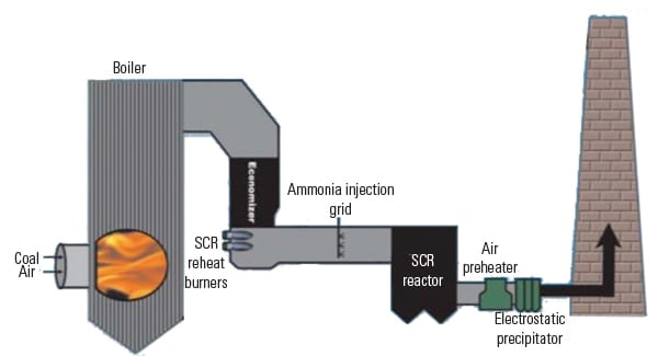
Operation of the gas diversion system is relatively straightforward (Figure 4). Diverter dampers and SCR outlet dampers are installed in the flue gas path and operated together to divert the flue gas through the SCR (SCR mode) or to bypass the flue gas around the SCR (SCR bypass mode). SCR mode is achieved with diverter dampers open toward the SCR and the SCR outlet dampers open. SCR bypass mode is obtained with diverter damper closed toward the SCR and the SCR outlet louver damper closed. NOx monitoring is performed before and after the SCR.
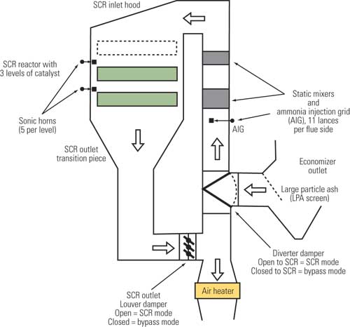
4. Pick your path. The flue gas path of each SCR system is illustrated. During the Phase 1 outage the existing economizer outlet flue was demolished, with the exception of the last 20 feet of the air heater inlet flue, and new diverter dampers and economizer outlet/air heater inlet flues were installed. Source: Hitachi Power Systems America Ltd.
Final Test Results
Preliminary performance testing results indicate that the SCR system has significantly outperformed its NOx removal guarantee of 90.3% reduction of NOx in the flue gas, from 0.413 lb/million Btu to 0.04 lb/million Btu. The ammonia slip, which was guaranteed at 2 ppm, was measured at 0.2 ppm. The SO2 oxidation was guaranteed at 0.5% and measured less than 0.1% across the entire SCR. The system pressure drop was measured at less than 5 inches of H 2 O — well under the guaranteed value. The precipitator particulate removal efficiency is 99.7%.
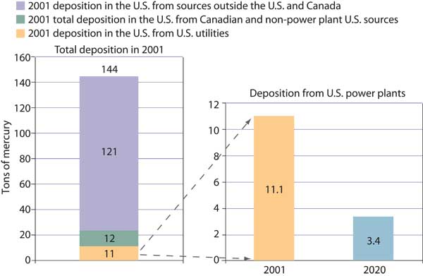
What about mercury? Prior to the pollution control enquipment upgrades, testing indicated that approximately 82% of the mercury was being removed. With the scruber upgrade and the addition of the SCRs, the removal rate increased to 90%.
After a decade of hard work and an investment of about $300 million, SECI can now say that the Seminole Generating Station has reduced its air emissions well below what is required by the plant’s air permit and has minimized its solid waste disposal problems with a robust recycling program. In fact, should the supercritical Unit 3 be built, the total air emissions of all three units will be less than those of just Units 1 and 2 a decade earlier. Few coal-fired plants can make these claims.
—Dr. Robert Peltier, PE is POWER’s editor-in-chief.