Most operators know that air should be kept out of a heat exchanger’s cooling water supply line. Air can collect in pockets and block flow, increasing velocities, increasing system resistance, decreasing effective heat transfer surface area, and degrading pump performance.
It may come as a surprise to hear that intentionally injecting air into the system is sometimes beneficial. Air injection is an effective way to reduce or prevent the damaging effects of a water hammer caused by transient vacuums. This article will discuss why and where vacuums can form, and how to size air injection valves to prevent problems.
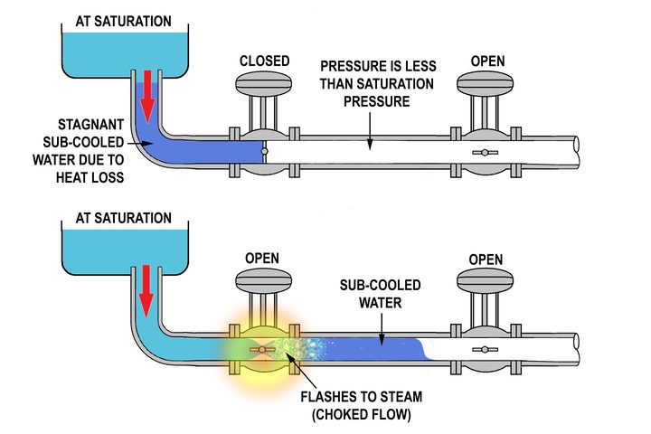
If the pressure in a pipeline drops to the water’s vapor pressure (approximately 0 psia [absolute pressure]), the water will begin to vaporize. This is known as “full vacuum,” which is as low as the pressure can go. Cavitation, which is the implosion of small vapor bubbles, will occur, and can lead to pipe and valve internal damage. Prolonged vaporization could allow water vapor to collect into a cavity large enough to break the water column. Afterward, when the pressure recovers or the vapor within the cavity flash condenses, the ends of the water column will violently snap back together, generating large pressure shock waves. Unexpected vacuum conditions also can cause piping to catastrophically implode.
How Transient Vacuums Form
A transient (that is, short time and temporary) vacuum can form during transitions between operating modes. When a pipe’s steady flow is interrupted by a rapidly closing valve, the pressure decreases on the downstream side (a down-surge), and builds on the upstream side (an up-surge). This generates a negative pressure pulse (shock wave), which travels downstream, and a positive pulse, which travels upstream. These pressure pulses travel at sonic velocity, and will in turn transmit inverted reflections back toward the valve whenever they reach a flow splitter (branch connection) or a flow area change.
Eventually the system will be filled with rapidly traveling positive and negative pressure pulses, adding and subtracting as they pass each other. The magnitude of the pulses created are directly related to the flow’s change in velocity (that is, deceleration) while the valve is closing. A down-surge combined with negative pressure pulses can temporarily drop the pressure in some areas to full vacuum. Similarly, a rapidly stopping pump will create a large down-surge and pressure pulses will form based on how quickly the pump decelerates when tripped.
These transient events are a form of “water hammer,” and are recognized by characteristic hammer-like noise accompanied by violent pipe shaking. In most cases, water hammer can be prevented by simply slowing down the initiating event.
Unfortunately, this is not always an option. For example, some valves must act quickly when responding to a demand change or a component’s failure.
Air Valves
Air injection is considered the most reliable method of water hammer protection against transient vacuums. The air will raise the pipe pressure as high as the outside pressure, thus stopping the vaporization process. Afterward, the trapped air pocket will act like a spring to cushion and prevent a violent collision between two separated water columns trying to rejoin. After the transient conditions are over, the injected air can be safely vented.
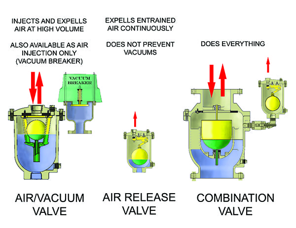
Many air valve designs have been developed for the purpose of injecting or releasing air. The options can be confusing, and they are frequently misapplied. However, the valves generally fall into one of three main categories (Figure 1): Air/vacuum valves, air-release valves, and combination valves. These categories can be further broken down into various sub-designs.
 |
|
1. Air valves. There are three main categories of air valves: the air/vacuum valve, the air release valve, and the combination valve. Source: Michael Czyszczewski |
Air/Vacuum Valves. These valves have two functions: To open to admit large amounts of air when vacuums form during pipe draining, and to expel large amounts of air when the pipe is being filled. The air flow in and out is controlled by a single large orifice that typically ranges in size from 1 inch to 20 inches, but sizes as large as 40 inches are available. A dropping float is used to open the valve to admit air when pipe pressure at the valve drops below atmospheric pressure. The air is expelled when the pipe pressure recovers and water enters the valve, lifting the float and closing the valve. In normal conditions when the pipe is pressurized, the valve is closed. These valves are prone to slamming shut during pipe-filling procedures, which can create a secondary pressure transient. Two subgroups of air/vacuum valves include the following:
■ Vacuum Breakers.This design is a variant with only the air inlet capability. The valve will quickly admit large amounts of air whenever the pressure inside the pipe where it is installed drops below the spring-controlled cracking pressure. When the pipe pressure recovers, the valve closes, trapping the air inside. The opening and closing pressure is about –0.2 psig (gauge pressure).
■ Well Service Air Valves. These valves are intended to be installed at the discharge of vertical turbine pumps. A small diameter valve orifice is used to allow air into the pump column after shutoff to prevent a secondary transient from forming. An air outlet throttling device is provided to cushion the release of this air at startup.
Air-Release Valves. The dissolved air content in water is on average 2% of its volume. When the water is depressurized or heated, this “free air” will come out of solution. Air can also become entrained in water when it enters the pump suction. These valves use a float to slowly open and continuously remove accumulations of free and entrained air. Orifice sizes of 1/16 inch to 1 inch are typical. These valves are not used for vacuum control, and they are not intended to be used for pipe draining and filling. However, this valve is commonly added to a vacuum breaker to provide a means of slowly removing injected air.
Combination Valves. These valves provide the function of both an air/vacuum valve and an air-release valve. A non-slam combination valve has an extra orifice that allows the valve to gently close in two stages when exhausting large amounts of air. This valve is a significant improvement that is strongly recommended over the standard design.
It is important that vacuum breakers be correctly sized and located, because their failure to perform could result in a catastrophic pipe failure. The valve opening (orifice) diameter determines the flow rate. The sizing methodologies typically followed are provided in the American Water Works Association (AWWA) Manual M51, as well as valve vendor catalogs. The sizing criteria are based on determining pipe fill rates, pipe break flow rates, dissolved air concentrations, and pipe collapse pressures. However, equations are not provided for transient vacuum control. A summary of equations for determining the orifice flow rates and diameters are available for download as part of the online version of this article, and the locations where transient vacuums can form are also summarized in a separate table (see here and here).
Evaluating Transients and Remedies
The hydraulic transients leading to vacuum formation are complex; therefore, they are best evaluated using one of many commercial incompressible flow pipe water hammer programs. This software greatly facilitates the design process by providing graphing and animation capabilities that make it easier to understand and visualize the system hydraulics. If problems are identified, the analyst can then use the software to troubleshoot the issues and size any required valves. Simulation software helps provide more certainty that all significant transient events are fully evaluated and that the correct type of valve is installed only where necessary.
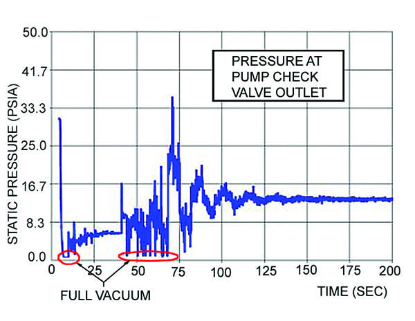
For example, consider the case where a vertical turbine pump is used to convey water uphill, through a condenser to a submerged exit at a lake. In this theoretical case, reverse flow is prevented by a fast-acting pump discharge check valve. Figure 2 shows the pressure-time history at a point downstream of the check valve after the pump is powered off. A pump trip would result in an abrupt down-surge to full vacuum, which creates some cavitation. Full vacuum pressures again form as the flow reverses and the check valve closes.
 |
|
2. Transient pressure spikes. The pressures generated after a pump trip show the creation of transient vacuums. Source: Michael Czyszczewski |
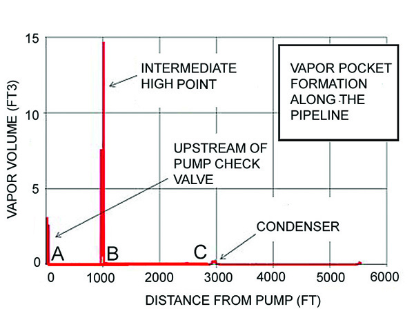
Locations for Vacuum Breaker Valves. A plot of vapor formation along the length of the pipe is shown in Figure 3. The peaks indicate where vacuum breakers may be needed: The pump discharge (A), an intermediate highpoint between the pump and condenser (B), and the condenser outlet (C). The effect of a vacuum breaker is highly localized to the general area where it is installed. Evaluate each area, one area at a time, starting with the area of greatest vapor volume (B).
 |
|
3. Vacuum locations. The locations along the pipe where vacuum-induced cavitation creates vapor pockets are highlighted here. The most vaporization occurs at an intermediate high point—location B—between the pump and condenser. The vaporization at location C is not significant. Source: Michael Czyszczewski |
Setting the Cracking Pressure. The analyst should make two steady-state runs, one with the pump operating (the initial state), and one with the pump off (the resting state), to obtain the pressures at the proposed valve location.
If the initial and resting state pressure (in psig) is positive, set the cracking pressure to atmospheric (0 psig). Actual valves will crack open at a pressure differential of about 0.25 psid (pressure differential) and will be full open at 2 psid, but this level of detail is not required in the model. If the initial or resting state pressure is negative, this could indicate the presence of a siphon. It is not uncommon to intentionally use the siphon effect to reduce the pumping power required. If a vacuum breaker is placed at this location, the siphon will be broken. The water column will separate and attempt to drain out of the piping. Locating a vacuum breaker on a siphon is not recommended and should be avoided.
If the resting state pressure is negative, a vacuum breaker will open and remain open until the system is restarted and becomes pressurized again. In order to close the valve sooner, a cracking pressure lower than the resting state pressure would be needed. Theoretically, a vacuum breaker that uses a compressed spring to control the pressure at which it opens should be adjustable. An electronically operated control valve using pressure signals would also be adjustable (but in the event of a power outage it would not be reliable without a backup power supply). Although adjustability is theoretically feasible, the author is not aware of any commercial air valve that promotes that it features an adjustable cracking pressure. In addition, many of the software programs discourage using a negative cracking pressure by making it difficult to input. Consequently, specifying a cracking pressure of other than 0 psig is not recommended.
Orifice Size. A vacuum breaker valve should be capable of injecting air at least at the same rate that the vacuum cavity forms. The valve orifice size determines the air flow rate. The nominal valve size describes the inlet size, which is not the same as the orifice size.
The air flow can be sonic or subsonic. If the orifice is too small, sonic flow occurs, which limits the mass flow rate, is very loud, and prevents the valve from fully raising the pipe pressure to atmospheric. Although cavitation will be prevented, sonic flow should be avoided. On the other hand, an orifice that is too large may not present any operational problems, but adds to the valve’s cost. Therefore, specify the smallest size that does not have sonic flow.
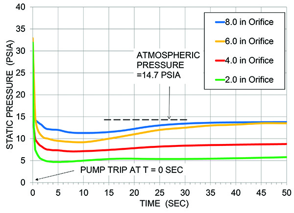
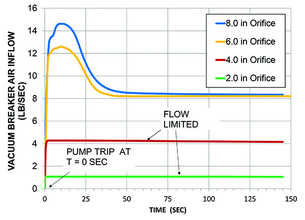
The process for determining the optimum size is to compare computer simulation pressure and air flow results from various trial orifice sizes. The effectiveness of orifice diameters of 2, 4, 6, and 8 inches are illustrated in Figures 4 and 5. The 2- and 4-inch trials show choked sonic flow because they are not able to raise the pipe pressure to atmospheric. The 6- and 8-inch trials show that full flow and atmospheric pressure will be attained. Based on these results, a 6-inch orifice would be the most economical option. Based on the type of valve end connections, orifice size, and system pressure class required, a suitable valve can be chosen from a manufacturer’s inventory.
 |
|
4. Vacuum pressures. This chart shows the effect of vacuum breaker orifice diameter on increasing the pipe pressure above full vacuum. Source: Michael Czyszczewski |
 |
|
5. Air injection flow rate. This chart shows the effect of various orifice diameters on the vacuum breaker air flow rate. Source: Michael Czyszczewski |
If an air-release valve will be provided as a vacuum breaker accessory, its outlet flow orifice can be included in the model. However, since it does not operate until after the transient is effectively over, the outflow orifice size is not critical, and is typically not modeled. The valve manufacturers provide simple charts that recommend which valve size to use based on only the header pipe size and flow rate. Pick a valve size that will give an outflow rate much lower (roughly 2%) than the vacuum breaker inflow rate, but high enough to evacuate the air in a reasonable amount of time.
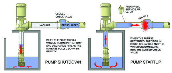
Vertical Turbine Pump Suction. The plot in Figure 3 shows that a vapor cavity formed upstream of the pump discharge valve (A). After a vertical turbine pump trips and its discharge valve closes, a vacuum will tend to form in the area between the closed valve and the pump inlet. This vacuum occurs as the water tries to drain out of the pump. A water hammer will occur upon startup if the vacuum is allowed to accelerate the water column into the closed valve as shown in Figure 6.
 |
|
6. Pump suction vacuum. A vertical turbine pump can experience a vacuum on shut-off. When the pump is restarted, the vacuum can cause a water hammer. The solution is to add a well service air valve near the pump discharge. Source: Michael Czyszczewski |
Air injection during pump shutdown will eliminate the vacuum. However, the injected air must be removed when the pump is started or it will be conveyed through the system, causing problems.
The well service air valve is specifically designed for this service. A small diameter orifice is used to allow air into the pump column after shutoff to prevent a vacuum from forming. At startup, a two-stage air outlet throttling device will prevent the water column from slamming the shut valve by gently releasing the air. Valve manufacturers provide charts that identify the best valve to use based on the pump flow rate shown on the pump curve at run-out.
Other Considerations
It is critical that the boundary conditions of the model accurately reflect the physical world. Systems with an open discharge will experience full or partial gravity drain-out of pipe sections during the transient. Drain-out can create pipe sections that are only partly water-filled, or outlet conditions that change from pressurized to atmospheric. Not all commercial software is capable of simulating a moving and changing boundary condition. Most software assumes the pipe is always full and the flow is single phase. The analyst must be familiar with the modeling limitations of the software and use sound judgment to ensure worst-case conditions were considered.
Vacuum breaker valves can fail to operate. Outdoor valves could freeze. Even a partial vacuum can cause a pipe collapse. Therefore, sections of piping that could experience a transient vacuum if the air valves fail to open must have their buckling strength checked (refer to equation 2 in Table 1, found online). If problems are identified, the strength of the pipe sections affected must be increased.
It’s been said that nature abhors a vacuum. However, if you have properly located and sized valves to inject air and eliminate any transient vacuums that attempt to form, you may feel differently. An essential tool for gaining this confidence is to make use of computer simulation. ■
—Michael F. Czyszczewski, PE (mczyszczewski@asme.org) has 40 years of experience with the design and specification of power plant components.