The Clean Air Interstate Rule (CAIR) is pushing utilities in 28 eastern states and the District of Columbia to retrofit many of their coal-fired power plants with selective catalytic reduction (SCR) systems to minimize NOx, and with flue gas desulfurization (FGD) systems (scrubbers) to do the same for SO2. The U.S. Environmental Protection Agency estimates that by 2015, when the CAIR regulations have been fully implemented, SO2 emissions will have been cut to 2.5 million tons a year, 73% below 2003 levels. By then, NOx will have been reduced by a similar amount—61% from 2003 levels. Because CAIR’s NOx and SO2 caps will begin to be enforced in 2009 and 2010, there’s currently a boom in construction of air quality control systems (AQCS).
Project overview
The environmental improvement project at Pleasant Prairie Power Plant (P4) was undertaken as part of We Energies’ plan to meet current and pending air quality improvement commitments and environmental regulations. The plant exemplifies the challenges of retrofitting complex SCR and FGD systems to a working power plant. Cost is one of those challenges. AQCS upgrades often cost many times the original capital cost of the plant due to competition for limited vendor shop capacity, shortages of qualified field labor, and rising material costs.
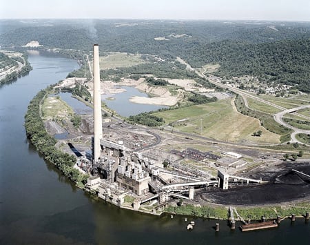
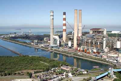
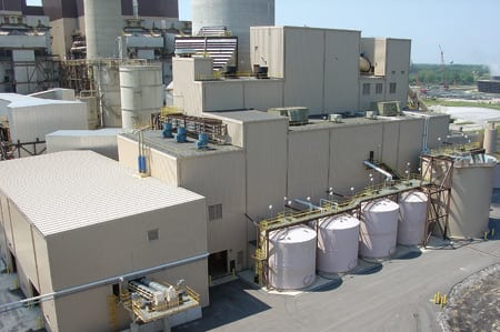
In many ways, P4 (Figure 1) is representative of the challenges facing utilities seeking the least-cost path to CAIR compliance. Its two 617-MW units were designed and built in the early and mid-1980s to burn pulverized Powder River Basin coal. Unit 2 was retrofitted with a hot-side SCR system in 2003. The current project added a hot-side SCR system to Unit 1 and a wet-limestone, forced-oxidation FGD system to both units. The configuration of the plant required installation of new booster fans and ductwork between the existing induced-draft (ID) fans and the new absorber vessels. A new, dual-flue stack (to serve both units) made of concrete and fiberglass-reinforced plastic (FRP) had to be added. The AQCS upgrades are capable of reducing P4’s NOx emissions by 90% and removing 95% of the SO2 from a design coal with a sulfur content of 0.5%.

1. CAIR package. We Energies’ twin 617-MW units at Pleasant Prairie Power Plant received a major air quality facelift. Unit 1 was retrofitted with an SCR system and a wet scrubber. Unit 2, which received an SCR system in 2003, received a new scrubber. Both units also share a new stack (shown at left). Courtesy: Washington Group International
All of the FGD system equipment (for absorption, reagent preparation, and gypsum dewatering) was supplied by Wheelabrator Air Pollution Control (www.wapc.com). The SCR system was provided by Riley Power Inc. (www.babcockpower.com). Overall project coordination and management were handled by Washington Group International (www.wgint.com). Washington Group’s scope included balance-of-plant engineering, procurement, construction, and commissioning. Emerson Process Management (www.emersonprocess.com) supplied the new systems’ distributed processing units, operator and engineering workstations, and network periphery gear, and integrated those elements into existing plant controls. Last but not least, Pullman Power (www.structural.net) built the new stack under a turnkey contract.
Unit 1’s SCR and FGD systems were placed into service in November 2006. The commissioning of Unit 2’s scrubber followed five months later, in April 2007. Exorcising the inevitable gremlins before those dates was challenging but necessary. Because both P4 units operate in baseload mode, the three new actors and their supporting casts need to be at least 98% available.
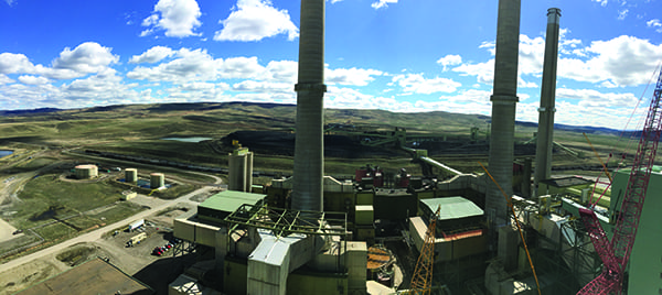
The SCR system for Unit 1 (Figure 2) is designed to reduce NOx emissions by 90% (a 30-day rolling average) when burning
the design fuel. That removal rate assumes a NOx concentration of 0.5 lb/mmBtu in the flue gas entering the system. The hot-side system consists of two reactor modules, each with two initial layers of catalyst and provisions for two more in the future. The catalyst type is Ti-V-W honeycomb, supplied by Cormetech Inc. (www.cormetech.com). Because P4’s air permit requires the SCR system to operate continuously, a reactor bypass is not included.
2. Clearing the air. The SCR system for Unit 1 under construction. The hot-side system is designed to remove 90% of NOx emissions, using aqueous ammonia injection. Courtesy: Washington Group International
NOx reduction in an SCR is achieved by mixing flue gas with ammonia in the presence of a catalyst. In the P4 SCRs, aqueous ammonia is injected at eight locations per reactor module. Effective mixing is ensured through the use of a Delta Wing static mixer supplied to Babcock Power by the Balcke-Durr division of SPX Corp. Both sonic horns and steam sootblowers are used to clean the SCR catalyst of ash buildup. This enhances the catalyst’s performance, reducing ammonia consumption and ammonia slip while still achieving high rates of NOx reduction.
Knocking its SOx off
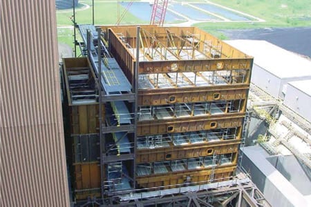
The FGD systems (Figure 3) are designed to remove 95% (30-day rolling average) of the SO2 produced when burning the design fuel. Wheelabrator guarantees that the stoichiometry of the scrubber’s limestone reagent will not exceed 1.03 under any conditions. All guarantees are being met with one absorber recycle pump out of service.
3. Scrubbing it down. The inlet to the absorber section of the new scrubber for Unit 1, shown during installation. The system is designed to remove 95% of the unit’s SO2 emissions when it’s burning coal with a sulfur content of 0.5%. Courtesy: Washington Group International
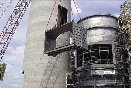
All FGD process systems have been placed in a common building (Figure 4). The reagent preparation equipment is located in the center, between the two absorbers. Adjacent to each absorber is a dedicated primary gypsum dewatering hydroclone. Shared vacuum filter systems and a common storage area have been located at the end of the building.
4. Compact "Scrubber Island." FGD process equipment, limestone preparation, and gypsum dewatering and storage equipment for both units are all housed in a compact design. Courtesy: Washington Group International
To expedite construction, the FGD building was designed and built in two phases. The bottom structural mat, designed during the project’s early stages, addressed general equipment arrangements, the placement of the FGD slurry pump and limestone ball mill equipment, and maximum floor loading limits. The design of the building’s framing, flooring, and major structural bracing systems was frozen for up to one year while the locations of vertical columns were determined to facilitate the bottom mat design. At that point, the final design was completed and the top mat—including the sumps, trenches, and equipment pads—was issued for construction.
Makeup and cooling water for the FGD process is supplied by P4’s existing cooling tower makeup system. The increase in demand required the upgrading of lakeside makeup pumps. Wastewater from the FGD process is discharged into the upgraded existing cooling tower blowdown system that drains into Lake Michigan, about five miles away.
The limestone used by the FGD process is delivered by truck, stored in an open pile on the plant site, and then sent via enclosed conveyor to replenish local day silos. The wallboard-quality gypsum that the scrubber produces is stored in an enclosed facility and later trucked offsite. Some 42,000 lb/hr can be produced when both units are burning the design fuel at full load.
P4 goes 3-D
A very interesting aspect of the AQCS upgrade project was its "availability by design" philosophy. To meet such an ambitious goal, Washington Group International and We Energies took a number of specific actions during the design process (see table).
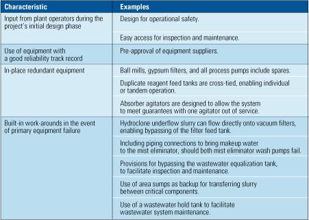
Availability by design. A specific program for maximizing system reliability and availability was developed for the Pleasant Prairie Power Plant project. Source: Washington Group International
Among them, but not shown in the table, was the development of a 3-D model of the plant to facilitate collaborative design reviews. The 3-D model included all equipment, piping/supports, cable tray, and structural members. Using MicroStation Smart Plant from Intergraph Corp. (www.intergraph.com), Washington Group, We Energies, and subcontractors’ site teams took a weekly walk though the design (Figure 5). The software and model enabled interactive reviews of valve and instrument locations, accessibility, egress, maintenance space, hoisting/removal plans, and the like. Without question, building the model was a terrific decision. Time and again it allowed design changes to be proposed, discussed, and finalized with minimal effect on project cost or schedule.
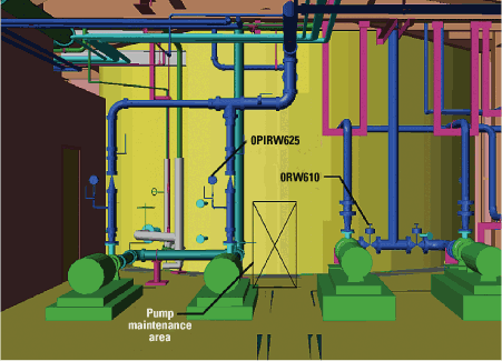
5. Virtual walk-through. Washington Group used 3-D engineering design tools to create a virtual representation of Pleasant Prairie Power Plant. The images were used in performance O&M studies and to identify design deficiencies prior to construction. Courtesy: Washington Group International
Ducts in a row
As an example of the benefits that high-tech design techniques brought to the project, consider how the configuration and sizing of induced-draft fans was optimized. Given the size of the major pollution-control systems to be added, Washington Group designers realized that they would require a substantial increase in overall fan capacity. But would it make more sense to get that capacity by replacing or upgrading existing ID fans, or by adding an ID booster fan or two? What about constant-speed versus variable-speed fans? Centrifugal or axial? After many design iterations, and with an eye toward equipment life-cycle costs, the final decision was made to install two new single-speed axial booster fans with blade pitch control in series with the existing ID fans.
For this project, mercury control was not included in the scope of work. However, Washington Group’s final design does anticipate the possible use of sorbent injection and fabric filter baghouses. It does so by making the ductwork between the old and new fans long enough to accommodate the addition of baghouses and conveyors, as well as silos for storing fresh and spent activated carbon sorbent, in the event that new rules require such control.
Once Washington Group’s engineers had determined the fans’ type and configuration, they next had to confirm the ductwork design. They outsourced that task to Airflow Sciences Corp. (www.airflowsciences.com), which used computational fluid dynamics (CFD) simulations and a 1/12th-scale physical model of P4’s AQCS to confirm three design characteristics: overall system pressure loss, uniformity of flow, and the reduction of opportunities for flyash to accumulate in ducts.
The velocity distributions generated by the CFD model (Figure 6, left) confirmed that the velocity profile of the ductwork was sufficiently uniform in critical areas. The physical model (Figure 6, right) endorsed the confirmations of pressure loss and flow via smoke testing, and that of ash accumulation via salt entrainment testing.
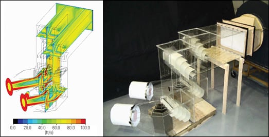
6. Second opinions. Booster fans were added before the ID fans on both units to overcome the higher backpressure produced by the addition of the SCR and FGD systems. Stability of the system was a concern, so CFD testing was required. Shown on the left is a 3-D velocity distribution taken from the CFD model; the booster fans’ discharge enters from the left, and the air exiting at right goes to the absorber inlet. A 1/12th-scale model (right) also was built and used to confirm that opportunities for ash accumulation in ductwork had been minimized. Courtesy: Washington Group International
Double stack
P4’s new stack is a slip-formed concrete structure that’s 430 tall and 67 feet, 7 inches in diameter. Designed by Pullman Power, it took one month of weekdays to erect at the average slip-forming rate of 1 foot per hour. Inside the stack are two fiberglass-reinforced plastic flue gas liners. Each liner is 26 feet, 7 inches in diameter (Figure 7). Both flues were field-fabricated and assembled on site. The resin used on the structural FRP wall was Hetron FR992. A 15-foot-high vertical mandrel was used to spin twelve 30-foot "cans" per flue, which were then placed in the chimney base and jacked into place one at a time.

7. Two in one. The interior of the new, 430-ft tall stack, showing the two fiberglass-reinforced plastic flues, one for each generating unit. Courtesy: Washington Group International
Construction challenges
Pleasant Prairie has the largest megawatt capacity in We Energies’ system and in the state of Wisconsin, making it critical to complete the project on time and within scheduled outage windows. Key aspects of the outage work—ductwork tie-ins; integration of a new, plantwide distributed control system upgrade; and electrification of the distribution system—were completed without impact to the outage schedule. Because most systems were tested prior to tie-in, start-up of the new equipment had minimal impact on plant availability. This major project also was brought on-line concurrent with other plant projects to complete a turbine overhaul and install a new superheater.
SCR construction had to take place above the existing coal delivery system and draft fan equipment, requiring significant crane support. The FGD was constructed in proximity to the plant’s ash-loading operations. Plant generation and delivery systems were not impacted during project construction. The project achieved more than 1,000,000 work hours without a lost-time incident.
Sharing the risks and rewards
The engineering, procurement, construction, and commissioning proposal prepared by Washington Group in the fall of 2003 established an initial price for the project, which then became the starting point for negotiating the target price. We Energies and Washington Group shared cost, schedule, startup, and performance risks as an incentive to reduce costs while meeting the target price. The target price estimate and associated technical description formed the baseline from which the project’s execution was monitored. As the design was fleshed out, changes in the estimate basis, and savings and cost additions, were tracked, recorded, and agreed to prior to being finalized. This approach ensured that the project team remained focused on the project’s goals while controlling its costs.
The project was initiated by a limited Notice to Proceed delivered to Washington Group’s Engineering department in November 2003. The first eight months were spent developing a well-defined project scope to establish the target price, starting with a "bottom-up" cost estimate. This kind of estimate required a significant expenditure of engineering resources to define the scope of work and to perform the technical studies and evaluations needed to establish the plant design basis and arrangement. It also necessitated finalizing configurations of the electrical and instrumentation systems, the material-handling approach, selection of fans, etc.
Once that was done, summary specifications were prepared for all equipment, subcontracts, and bulk materials. The specifications then were used to solicit vendors and establish target prices. The initial critical activities included the award of the contracts for FGD equipment supply and for designing and erecting the stack. Upon completion of the civil/structural design in the spring of 2004, a full Notice to Proceed was issued and construction began.
—Steven Gebhart (steven.gebhart@wgint.com) is the project manager, Dennis Pennline (dennis.pennline@wgint.com) is project engineering manager, and Ira Brodsky (ira.brodsky@wgint.com) is lead process engineer for Washington Group International on the We Energies Pleasant Prairie Power Plant Air Quality Control Upgrade Project. Dan Bichler (dan.bichler@we-energies.com) is project manager for We Energies.