It has been more than two and a half years since the Environmental Protection Agency (EPA) issued national emission standards for hazardous air pollutants from coal- and oil-fired electric utility steam generating units (EGUs), and standards of performance for fossil fuel–fired electric utility, industrial/commercial/institutional, and small industrial/commercial/institutional steam generating units. Specifically, the rule created mercury and air toxics standards (MATS) designed to reduce emissions from new and existing coal- and oil-fired EGUs.
Existing sources have up to four years, if they need it, after the final rule became effective—April 16, 2012—to comply with MATS. The period includes three years provided to all sources by the Clean Air Act and an additional year the EPA allows state permitting authorities to grant, as needed, for technology installation. In other words, power plants have less than one year left to comply with the rule, unless granted the additional one-year extension by their state.
While MATS compliance strategies have been covered extensively (see “Using Neural Network Combustion Optimization for MATS Compliance” in the February issue and “The Role of Activated Carbon in a Comprehensive MATS Strategy” in the March issue of POWER), in this article we will try to touch on a few key operational best practices that will help plants meet the new EPA requirements.
Tuning Up
To comply with the performance tune-up work practice requirement, each facility must demonstrate continuous compliance by conducting a combustion process tune-up, a thorough equipment inspection, and an optimization to minimize generation of CO and NOx. The work practice requirement must be completed at least once every 36 calendar months (or 48 calendar months if a neural network is employed). The work practice involves: maintaining/inspecting burners (Figures 1 and 2) and associated combustion controls; tuning the specific burner type, as applicable, to optimize combustion; obtaining and recording CO and NOx values before and after burner adjustments; keeping records of measurements and adjustments (Figure 3); and submitting a report for each tune-up conducted.
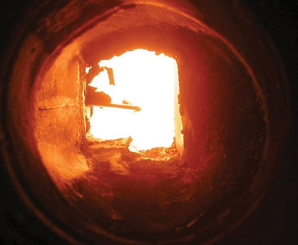 |
| 1. Nozzle deterioration. Low primary airflow resulted in damage to this burner. Courtesy: Storm Technologies |
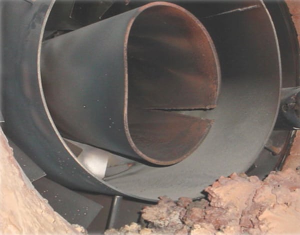 |
| 2. Burner geometry. It is essential for mechanical tolerances to be within one-quarter inch of design specification. Courtesy: Storm Technologies |
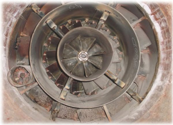 |
| 3. Good as new. Following repairs, the burner will fire more efficiently. Courtesy: Storm Technologies |
A combustion tune-up will involve optimizing combustion of the unit consistent with the manufacturer’s instructions, as applicable, or in accordance with best combustion engineering practices for that burner type. Under the final rule, the tune-up must be conducted at each planned major outage and in no event less frequently than every 36 calendar months, with an exception that if the unit employs a neural network system for combustion optimization during hours of normal unit operation, the required frequency is a minimum of once every 48 calendar months.
Initial compliance with the work practice standard of maintaining burners must occur within 180 days of the compliance date of the rule. The initial compliance demonstration for the work practice standard of conducting a tune-up may occur prior to the compliance date of the rule, but it must occur no later than 42 months (36 months plus 180 days) from the compliance date of the rule or, in the case of units employing neural network combustion controls, 54 months (48 months plus 180 days). Adequate records must be maintained in order to show that the tune-ups met the requirements of this standard.
Boiler Tune-Up Requirements
The work practice standards for boiler tune-ups require inspections of the burners and combustion controls. Should issues be found with the burners or combustion control components that affect the ability to optimize NOx and CO, these items must be installed/corrected within three calendar months after the burner inspection. Burner or combustion control component parts that do not affect the ability to optimize NOx and CO may be addressed on a timetable determined by the plant.
Boiler tune-ups are to include visual inspection of flame pattern, damper observations, evaluation of windbox pressures and air proportions, and inspection of the air-to-fuel control system.
Combustion should be optimized to minimize generation of CO and NOx, with adjustments made consistent with the manufacturer’s specifications or best combustion engineering practice for the applicable burner type. Optimization includes burners, overfire air controls, firing system improvements, neural network or combustion efficiency software, control systems calibrations, adjusting combustion zone temperature profiles, and add-on controls such as selective catalytic reduction and selective noncatalytic reduction systems.
Testing and tuning should be completed at full load or unit normal operating load. Figure 4 shows an actual CO, NOx, and O2 curve developed during testing/tuning that was completed.
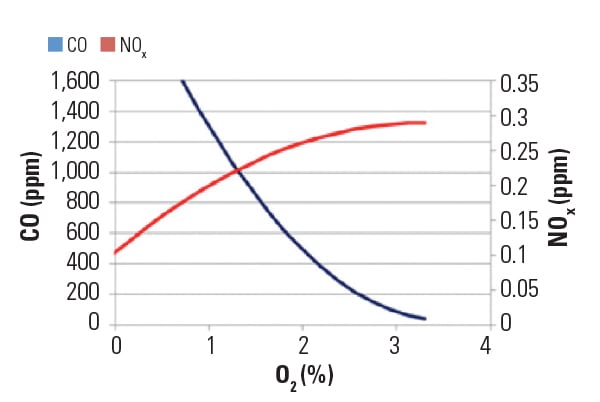 |
| 4. An inverse relationship. The curves show the effect excess O2 has on CO and NOx. Courtesy: Storm Technologies |
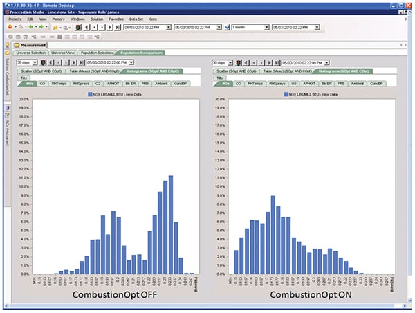
The EPA has amended the work practice and management practice tune-up standards to clarify that CO measurement, required before (Figure 5) and after (Figure 6) tune-ups, may be taken using portable CO analyzers. The requirements to inspect burners and the system controlling the air-to-fuel ratio may be completed during the next scheduled shutdown. Units that produce electricity for sale may also delay these inspections until the first outage, not to exceed 36 months from the previous inspection. Optimization of CO emissions must also regulate NOx within the given emissions limits. For units that are not operating when a tune-up is required, the tune-up must be conducted within 30 days of startup. ■
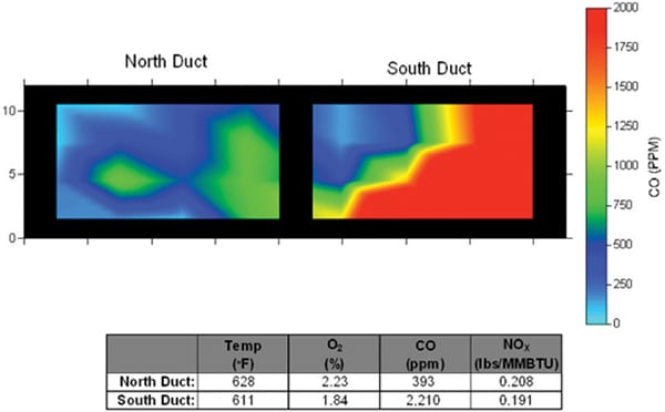 |
| 5. Before. The imagery shows significant differences between the north and south ducts. Courtesy: Storm Technologies |
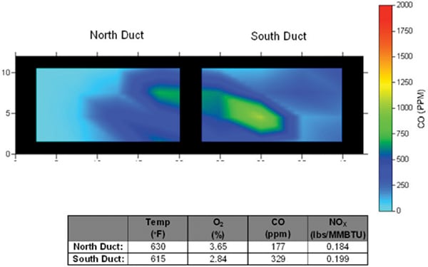 |
| 6. After. Following tuning, there was much less variation between the ducts. Courtesy: Storm Technologies |
—Danny S. Storm is president and COO of Storm Technologies Inc.