At Morgantown Generating Station, plant personnel used innovative methods to combine model predictive control with distributed control system–based process control algorithms to improve waterwall temperature control and main steam temperature control and to enhance unit ramp rate capability. The previous heat rate and NOx optimization performance gains were retained. Focusing beyond basic loops of feedwater, air, and O2, the project considered issues such as PID controller override configuration and limitations. The techniques used to overcome these challenges improved unit ramp rate capability beyond any previous unit performance.
The typical coal-fired power plant has been updated with digital controls and other performance and environmental improvements by the time it reaches middle age. Units 1 and 2 of GenOn Energy’s Morgantown Generating Station—which is situated on the Potomac River near Newburg, in Charles County, Md.—represent that class of plants with a twist. Over the years, a widening of the coal specifications and modifications to coal mill equipment adversely affected waterwall outlet steam temperature control and thereby unit ramp rate. With a recent emphasis on economic dispatch of the two units, those ramp rates had to increase in order to remain competitive.
Morgantown’s two units are are split- furnace 630-MW coal-fired once-through units constructed in the 1970s. The plants were retrofitted in the mid-1990s with low-NOx burners. A modern distributed control system (DCS) also was installed at that time, enabling significant control and ramp rate improvement. Furthermore, a dynamic NOx/heat rate optimization system (based on model predictive control and neural nets) combined with an intelligent sootblower optimization system were integrated with the DCS in 2006 to meet near-term NOx objectives.
Plant Profile
Each unit consists of a single tandem-compound turbine generator and a single pulverized coal-fired once-through controlled circulation supercritical boiler utilizing a single reheat-regenerative cycle. The steam generators are, in essence, twins; the turbine generators are of like capability but were designed and built by two manufacturers.
Unit 1 (Westinghouse) has a nameplate rating of 572.5 MW; the Unit 2 (General Electric) rating is 575.2 MW. Both units have throttle steam conditions of 3,500 psig, 1,000F, reheat steam temperature of 1,000F, and seven stages of feedwater heating.
Both 625-MW steam generating units were designed and manufactured by Combustion Engineering Inc. and are designed to deliver maximum continuous steam at a rate of 4,250,000 pounds of steam per hour with steam pressure of 3,810 psig, and steam temperature of 1,005F at the superheater outlet. The units were placed into service in 1970 and 1971.
The State of the Control System
The units were retrofitted with the original equipment manufacturer’s Low NOx Concentric Firing System II in 1994. This retrofit necessitated replacement of the original electric analog control system with a modern DCS. The DCS allowed for continuous unit improvements through the implementation of increasingly advanced control strategies. Automatic control in the low-NOx mode was extended to equipment-limited maximum generation capacity. Robust urgent and emergency plant and component protection required runback rates of 50% per minute and rundown rates of 70 MW per minute at maximum load in order to maintain operating pressures, temperatures, and excess oxygen (O2) levels within safe ranges.
Morgantown’s relatively low-cost generation placed economic priority on environmental and capacity goals. Unit maneuvering speed affected economics briefly during the spring and fall months and was not a high priority. The controls were adjusted for operation at 5 MW per minute.
Unit Ramp Rate Performance
Mechanical alterations took place on the pulverizers mostly due to coal supply changes. As a result, the DCS-mill modeling (originally designed for the typical coals) became more and more obsolete due to the changing coal supply. The modeling estimated fuel Btus released in the furnace vs. coal feeder speed based on pulverizer motor amps and was utilized to keep O2, airflow, and feedwater coordinated.
With increased variability of fuel supply, the control of furnace parameters degraded. One symptom was the increasing variability of waterwall outlet temperature toward its low and high alarm limits during load ramps. Due to these limitations, the operations team would frequently provide assistance by adjusting the waterwall temperature setpoint bias. In extreme cases, the operator would place the firing trim controller in manual mode and thereby assume waterwall and main steam temperature control. Another way to limit temperature variation was to reduce the MW rate-of-change, which was done with increasing frequency.
The final and most significant mill modification was the addition of a variable-frequency drive to power a new exhauster fan motor while retaining the original motor to drive the mill itself. The pulverizer upgrade also included the addition of new bowls for the dynamic classifier and new vane wheels. Before the upgrade, the pulverizers were limited in airflow capability. This resulted in a very narrow range of coal feed during which the exhauster inlet damper was modulated.
Full open damper position was reached at a coal flow equating to mid-boiler load, and the air/fuel ratio decreased as coal flow increased due to the lack of exhauster fan capacity. The mill upgrades provided increased mill capacity as well as sufficient exhauster fan capacity to control air/fuel ratio at the optimum value throughout the entire coal feed range. Mill fuel delivery response time was reduced, eliminating the need for the previous variable mill modeling techniques.
MW Ramp Rate Improvement Project
Plant management desired improvement of MW ramp rate for each steam unit because physical changes to the equipment had caused a degradation of MW ramping performance. Market conditions also converged to increase the economic benefits of more rapid load dispatch. Due to these factors, a ramp rate improvement project was commissioned to apply economical control changes for Unit 2. The primary technology employed for this project was Invensys Connoisseur model predictive control, an advanced process control solution.
Ramp Rate Limitations Prior to Control Modifications
Figure 1 presents 10 hours of load ramp data compiled during December 2008 prior to the control and optimizer modifications of the ramp rate project. An operator increased the ramp rate limiter from 3 to 5 MW/min. This trend presents the load, waterwall trim controller measurement, setpoint and output, firing master output and feedwater demand, north and south superheat temperature and setpoint, four desuperheat spray valve demands, and the spray differential pressure (dP) controller demand.
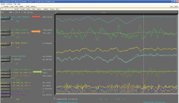 |
| 1. Ramp rate limitations. Steam temperatures during dispatch at 5 MW/min are shown (green arrow) prior to the installation of control modifications. While the north superheat temperature was controlled close to the setpoint, the south superheat temperature frequently dipped to low values (green arrow). Load ramping (red arrow) caused large variations in waterwall outlet temperature (orange arrow) that approached the high and low temperature alarm limits. The white vertical time line indicates a south superheat temperature of 962F. Courtesy: GenOn Energy |
Load ramping caused large variations in waterwall outlet temperature that approached the high and low temperature alarm limits. Although the north superheat temperature was controlled close to setpoint, the south superheat temperature frequently dipped to low values. The white vertical time line indicates a south superheat temperature of 962F. This low temperature persisted for a substantial period, resulting in a heat rate performance penalty. Due to these types of control challenges, the unit ramp rate was typically limited to 3 MW/minute by the operations team.
Main Steam Temperature Override Protection
The south superheat temperature exhibited an occasional dip during unit ramping. The dip was caused by an override controller limiting high output of the waterwall outlet temperature controller and thereby temporarily limiting the upward fuel bias to the unit and causing a drop in the low side superheat temperature.
In this case, the override controller responds to the highest of the four desuperheater inlet temperatures and reduces the waterwall outlet temperature controller output if the desuperheater inlet temperature exceeds the override setpoint.
Figure 2 presents a 1-hour portion of Figure 1 and includes the A1 desuperheater inlet temperature, which is the highest of the four desuperheater inlets. The white vertical time line has been placed at the 1,010F point, which is the setpoint for this override controller. Since the temperature remains above the override controller setpoint for several minutes, the waterwall outlet temperature controller output decreases, even though the waterwall outlet temperature is below the primary controller setpoint. As soon as the desuperheater inlet temperature drops below setpoint, the output of the waterwall outlet temperature controller begins to increase. However, the delay in the increase of fuel causes a dip in the south superheat temperature.
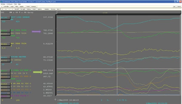 |
| 2. Temperature override protection. The desuperheater inlet steam temperature override is shown during dispatch in a 1-hour portion of Figure 1. In this case, the override controller responds to the highest of the desuperheater inlet temperatures (green arrow) and reduces the waterwall outlet temperature controller output (violet arrow) if the desuperheater inlet temperature exceeds the override setpoint. Courtesy: GenOn Energy |
Main Steam Override Protection: Flex Tuning
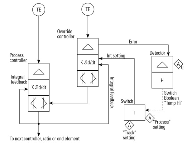
A protective circuit provided within the DCS is an override to the waterwall temperature controller fuel bias if main steam, main steam desuperheater inlet, or reheat steam temperatures exceed a predetermined value. Its function is to protect boiler tubes from excessive temperature and associated tube life degradation. Proportional-integral-derivative (PID) controller override functions were configured in the past (Figure 3).
 |
| 3. Typical override controller configuration. A protective circuit provided within the DCS is an override to the waterwall temperature controller fuel bias if the main steam, the main steam desuperheater inlet, or the reheat steam temperatures exceed a predetermined value. The function is to protect boiler tubes from excessive temperature and the associated tube life degradation. Courtesy: GenOn Energy |
However, tuning of the override controllers was compromised due to the functions of the PID series algorithm with external integral feedback. Specifically, a single feedback integral setting cannot be set at a “rate” fast enough to allow for appropriate “tracking” of the downstream controller while preventing premature action on the downstream controller. As a consequence, the setpoint for the override controllers to start action is usually not ideally set. In addition, the gain setting of the override controller must consider this interaction instead of the best process control override action. There are several methods to address such override control limitations. The remainder of this article describes the method developed and implemented for this project.
Why does compromised tuning take place in a normal override configuration using a PID controller? The answer lies in seeking the best integral setting for the override controller. Consider the scenario. The output of the standard PID controller with external integral feedback is equal to the error between the setpoint and measurement, multiplied by the gain, summed to the integral feedback, as illustrated by Figure 4.
Normally, many users of this algorithm in a single-loop strategy will connect the controller output directly to the integral feedback to provide the positive feedback loop and integration. However, the integral feedback is through a d/dt filter such that a lag exists. Essentially, if the setpoint-to-measurement error is zero, the output will be equal to the integral feedback after the lag time. The “conventional/ideal” override controller should track the primary controller when normal control action does not cause the measured variable to exceed the override controller setpoint. And it should provide robust control action when the measured variable does exceed the override controller setpoint. This creates a “Catch 22” for selecting the best integral setting for the override controller, because a very low integral time constant is needed in the track condition, and that setting is not compatible with tuning the controller for desired control response (Figure 4).
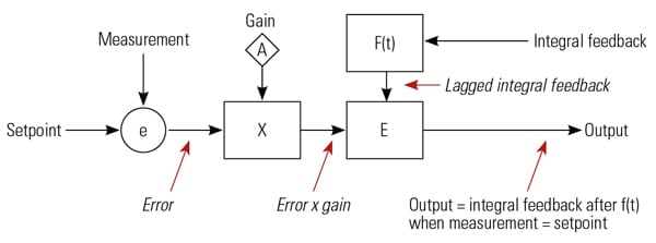 |
| 4. Series PI algorithm with external feedback. The output of the standard PID controller with external integral feedback is equal to the error between the setpoint and measurement, multiplied by the gain, summed to the integral feedback. Courtesy: GenOn Energy |
The output of the process controller may change rapidly due to process measurement vs. setpoint error. The process controller output is connected to the integral feedback of the override controller. Thus, the output of the process controller is always equal to the integral feedback of the override controller. However, internal to the override controller, the lagged integral feedback may not be this value, as it is a lagged signal. The lagged signal internal to the override controller may be lower than the output of the process controller. The proportional action (the difference between the setpoint and measurement) within the override controller is constantly active, summing up the lagged integral feedback. This value, though not at a point where override action is desired, summed up with the lagged integral feedback, can cause override action to take place.
A main project goal was to avoid this problem and tune the override controller to provide the optimal control action on the process, utilized to protect boiler components.
A successful new method was developed, using a single switch toggled by a Boolean derived from the measurement-to-setpoint error of the override controller, as shown in Figure 5. When the error is in the direction that no override action is necessary (the temperature measurement is lower than the setpoint), the Boolean is false. However, when the error is just slightly in the direction that override action is desired, the Boolean becomes true.
 |
| 5. Leveraging Boolean logic. A successful new control method was developed using a single switch toggled by a Boolean derived from the measurement-to-setpoint error of the override controller. For example, when the error is in the direction that no override action is necessary (the temperature measurement is lower than the setpoint), the Boolean is false. However, when the error is just slightly in the direction that override action is desired, the Boolean becomes true. Courtesy: GenOn Energy |
When the switching Boolean is false, the output of the switch is set to a very low integral time, effectively changing the internal controller f(t) to a following mode—that is, with minimal lag. When the Boolean is true, the switch utilizes the optimum tuning value to control (override) the process.
This method was tested repeatedly, utilizing false low override setpoint values. In addition, the method came into play under actual unit dispatch conditions and in each case performed well.
Model Predictive Control: Waterwall Temperature Setpoint
The fuel trim is regulated by the waterwall temperature controller in the base control design. If the waterwall temperature increases above the setpoint, the fuel is trimmed back and vice versa. The waterwall temperature setpoint is based on a load curve with an operator bias input.
The fundamental control requirement is maintaining superheat temperature near the setpoint. The final superheat control is regulated through superheat sprays. However, the waterwall outlet temperature strongly impacts the downstream superheat steam temperature. Prior to this project, the operator applied his knowledge of the impact of load ramping to adjust the waterwall temperature setpoint bias to maintain the superheat sprays within control range and thereby hold superheat temperature close to setpoint. However, with increased ramp rate, modulating this bias became a greater challenge to the operator.
The fundamental relationships between the waterwall temperature’s setpoint bias and the superheat temperature control loop aligned well with a model predictive control strategy. Therefore, the existing NOx/heat rate optimization system, which applies the dynamic model predictive/neural net combination, was expanded to include the waterwall temperature setpoint bias. Prior functionality of the optimization system was retained.
Post-Project Ramp Rate Results
Figure 6 presents a snapshot of the unit performance during normal dispatch operation after completion of the ramp rate project control enhancements. The configuration of flex tuning greatly reduced the amplitude and duration of the superheat steam temperature dips by allowing quicker response of the firing trim when the override condition is no longer active.
 |
| 6. Improved ramp rate results. This snapshot shows the unit performance during normal dispatch operation after completion of the ramp rate project control enhancements. The configuration of flex tuning greatly reduced the amplitude and duration of the superheat steam temperature dips (green arrow) by allowing quicker response of the firing trim when the override condition is no longer required. Note how unit load (red arrow) responds quickly to a change in the firing master (orange arrow). Courtesy: GenOn Energy |
The dispatch rate was set between 8 MW/min and 12 MW/min during this operational period. Load varied from a maximum of 630 MW to 390 MW. During the last 8 hours, there was also a transition to a much lower heating value coal, illustrating satisfactory ramp rate performance over a wide range of coal quality.
The peak north and south superheat temperatures were closely controlled near the setpoint throughout. Waterwall outlet temperature variations were kept well within alarm levels. All other steam temperature associated control loops indicated responsive control meeting the dispatch requirements.
There were several brief periods during which the south superheat temperature fell below the setpoint; those periods were consistent with periods of low waterwall temperature. These periods were caused by an override controller limiting the firing trim and providing protection from high temperatures at the inlet to the desuperheat sprays. Prior to configuring the flex tuning of the override controllers, these superheat temperature dips were excessive.
Based on the favorable control of final superheat temperature and waterwall temperature, the trend demonstrates that the ramp rate control enhancements are equally beneficial for both higher and lower heating value coals spanning a wide range of load.
Performance Update
The original objective of this project was to increase the ramp rate capability of both units and reduce the impact of high-temperature-override action on ramp rate. The scope of the project was recently expanded to apply the model predictive control system to reduce the frequency and duration of high-temperature-override incidents during ramping.
The system changes have enhanced the balance of steam temperatures throughout the boiler, overcoming a particular challenge in split-furnace boilers. The result has been the near-elimination of high-temperature-override incidents during ramping.
Further benefits have accrued from the system changes including these: sustainable fast ramp rate capability from near minimum load to near maximum load, the limitation of transient high temperatures of internal boiler components, and minimization of associated thermal stresses. The upgrades have been successfully implemented on both units.
The complex control strategies necessary to protect boiler tubes and other high-temperature equipment can have a deleterious impact on unit ramp rate potential. Through a combination of flex tuning and model predictive control, the limitations were overcome at Morgantown, allowing quadruple increases in the unit ramp rate while protecting boiler components from thermal stress.
This article is based on a paper presented by the authors at the 15th Annual POWID/EPRI Controls and Instrumentation Symposium. Morgantown Generating Station was the ISA POWID 2008 Facility of the Year.
— Donald Andrasik (don.andrasik@genon.com) and John McNulty (john.mcnulty@genon.com) are senior DCS engineers for GenOn Energy at Morgantown Generating Station. John Gay (powermaxc@aol.com) is president of Power Max Consulting Inc. and is an ISA Fellow. Don Labbe (donald.labbe@invensys.com) is a consulting control engineer for Invensys Operations Management. He is an ISA fellow and director for ISA POWID.