The enhanced plant performance achieved at the 1,477-MW Morgantown Generating Station shows the value of model predictive control in conjunction with intelligent distributed control algorithms. This project update looks at how the project team moved from ramp rate improvements to reducing tube metal temperatures to improved component life.
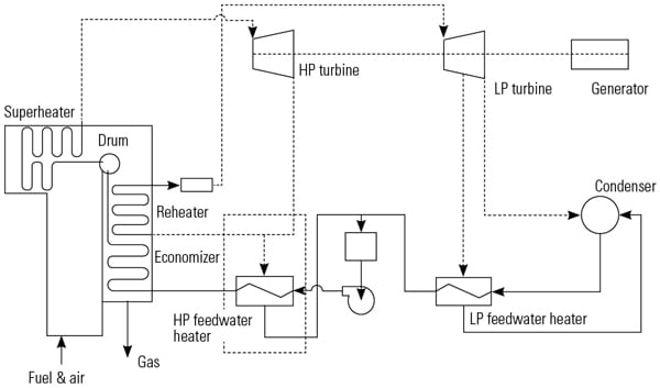
Morgantown Generating Station is on the Potomac River in Charles County, Maryland. Each unit consists of a single tandem-compound turbine generator (one Westinghouse and the other General Electric) and a single pulverized coal–fired once-through controlled circulation supercritical boiler utilizing a single reheat-regenerative cycle. Each has a nameplate rating of 572.5 MW with throttle steam conditions of 3,500 psig, 1,000F and reheat steam temperature of 1,000F and seven stages of feedwater heating. The units are capable of generating 625 MW each and were placed into service in 1970 and 1971.
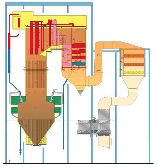
The Combustion Engineering steam generators are a balance draft divided furnace type, consisting of a tangentially fired, center wall furnace with economizer, and superheater and reheater surfaces.
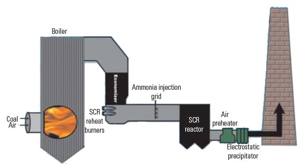
The split furnace design with dual selective catalytic reduction (SCR) systems poses unique challenges to balancing steam temperatures and limiting peak metal temperatures in the various boiler circuits. Because high peak metal temperatures are often a precursor to premature tube failure, control enhancements that decrease peak temperatures offer substantial payback to GenOn, the plant’s owner.
Through the expansion of the model predictive control within the dynamic nitrogen oxide/heat rate optimization system and additional distributed control system (DCS)–based process control algorithms, the objectives of improved steam temperature balance in the boiler circuits and lower peak metal temperatures were achieved.
These control improvements widened the load range of fast dispatch operation while protecting boiler tubes from excessive thermal-induced stress, promoting long boiler tube life. After instrumentation failures, boiler tube leaks cause more unit forced outages than any other component failure in the typical steam plant.
The experiences on Unit 2 are described in this article. The methodologies were then applied to Unit 1, and results were essentially similar, if not better. Earlier Morgantown control upgrades were described in “Increasing Generation Ramp Rate at Morgantown Generating Station’s Coal-Fired Units” in the February 2011 issue, also found in the POWER archives at https://www.powermag.com.
SCR Impact on Boiler Component Water/Steam Temperatures
Morgantown’s units experienced increasing temperature excursions on the platen superheater outlet temperatures at both the lower ramp rates and the newer, higher ramp rates. Previously, the original temperature override on the waterwall outlet trim would suffice to protect the component tubes in the rare case of high temperatures. After the SCR startup, the temperature excursion increased both in severity (peak temperature) and in frequency. This was especially true at minimum generation points and during generation load ramp increases from lower generation points.
The SCR catalyst requires a minimum temperature to ensure burn-off of any contaminate formation (ammonia bisulfate). To maintain the SCR catalyst temperature in each furnace in the split furnace design, an economizer bypass system takes heat from the gas path flow through the economizer and diverts it to the SCR inlet to maintain the minimum temperature requirement. This greatly decreases the water side fluid temperature out of the economizer. The waterwall temperature control then moves to increase the furnace firing rate to make up this loss and maintain the waterwall outlet temperature. As a result of the furnace gas flow redistribution, significant increases in platen superheater outlet temperatures threaten the tube material’s thermal limits.
Late-night testing at the lower generation points illustrated the effect of SCR temperature control (economizer bypass dampers with backpressure dampers on each individual furnace) on platen temperatures. Manipulation of the economizer bypass provided only marginal changes on platen outlet temperatures.
Another test revealed that the burner tilts had a greater influence in lowering platen temperature at a minimum generation point. However, there was an increasing difference between the individual split furnace steam temperature outlets as detected by the boiler throttle (BT) links feeding the platen superheater. Because of the split furnace design, one side may be relatively cooler than the other, but the main steam sprays will produce the desired outlet temperature. One side sprays excessively, while the other sprays with little to no flow.
The side that is spraying has a high platen outlet temperature, pushing undesirable thermal limits of the component tubes. So this temperature difference control now becomes a key objective, as it is desirable to keep both sides near balanced, thereby lowering peak temperature on the high-temperature side.
The difference between the furnaces is attributed to the established SCR temperature requirement and the economizer damper arrangement that was placed into service. There also can be imbalances of fuel/air distribution at the furnace input such as windbox and coal mill pipe distribution and an influence from sootblowing, or lack thereof, from side to side. Some of these can be controlled by operation; others may take a longer-term approach to rectify. The overriding plant requirements, however, are to eliminate or significantly reduce the temperature excursions as quickly as possible.
Sootblowing is set up on an intelligent model-based program that could help, but it shuts off below a mid-generation point. When generation is above this point, however, sootblowing can augment the control, decreasing the temperature difference between the waterwall furnace outlets in addition to maintaining furnace specific main steam temperatures and reheat temperatures.
As an intermediate step, the setpoint was decreased on the desuperheater inlet override for the waterwall temperature control. This provided some improvement, yet not to the extent desired for protecting the component tubes of the platen superheater; therefore, additional enhancement was needed.
Unit Front-End Slowdown
To protect the unit precipitators and the scrubber, which provides flue gas desulfurization (FGD), a DCS function has been implemented to slow down the unit ramp rate. This helps if opacity to the FGD (outlet of the precipitators) becomes too high. The opacity occurs as a result of precipitators experiencing unacceptable levels of furnace ash loading. The opacity also results from the high ash content loading to the FGD.
The algorithm employs mechanisms to ensure signal quality by a software type “deadman” function. This function is programmed without the use of an external signal from the monitoring instrument, as none is available. This program ensures signal health and validity. If high opacity is detected from the precipitator to the SCR equipment, the unit front end control will slow down the unit’s ramp rate proportionally in relation to the value of the opacity level.
MPC Model Development
At higher generation loads, the burner tilts and the waterwall outlet temperatures as measured by the BT valve links exhibited a significant consistent relationship in the modeling tools. In essence, the model predictive control (MPC) model identified the influence of tilts on the distribution of furnace heat input between the furnace radiation area and the convection pass at the higher load points.
Integrating the model into the predictive control produced noteworthy results. The burner tilts went under the management of the MPC with major weight given to maintaining the two furnace sides’ waterwall outlet temperatures and less weight given to the reheat temperature control. The reheat spray control within the DCS processor was revamped to ensure control of the reheat temperature should the new model control cause higher-than-desired temperatures. The reheat sprays functioned to control this temperature and have not become excessive. This change minimized any heat rate penalty, as the MPC does not allow the tilts to generate excessive reheat temperature.
The MPC is utilized in conjunction with previously implemented furnace-to-furnace bias model control. The MPC manipulates the secondary air bias between the furnaces based upon the desuperheater temperatures of each furnace side, along with carbon monoxide delta between each furnace side.
The furnace-to-furnace model bias control offsets the influence of the gas flow imbalances, functioning as designed. However, there is a limitation at lower generation. To maintain cooling air on the secondary air registers requires a minimum opening. As the steam generator load point is decreased and the secondary air registers reach this minimum flow limit, the furnace-to-furnace bias is reduced in a proportional fashion to the point where it reaches zero and can no longer influence furnace-to-furnace distribution.
Additional predictive control utilizing the desuperheater inlet temperature as a modeled constraint on the manipulation of the waterwall temperature setpoint is set in place. This lowers the effect of firing in reducing both furnaces’ platen temperatures and thereby significantly reduces the platen outlet peak temperatures. In other words, the predictive control “rounds-out” the platen superheater temperature increase before reaching undesirable values.
During the performance analysis of the furnace, further furnace modeling needs became apparent. The unit exhibited a changing characteristic of radiation dominant to the convection dominant with respect to load. The effect of the burner tilts on temperature distribution changed as a function of load. That is, lowering the reheat tilts produced different results at high loads versus low loads. At lower loads, decreasing the tilt position assisted in lowering platen superheater temperatures; at higher loads the opposite is true. Additionally, there was a significant change in waterwall temperature control in regards to the boiler recirculation as the pump recirculation loop check valve opened at lower loads. Both of these issues necessitated different model usage based upon load.
SCR Impact on Boiler Heat Absorption
Historical boiler temperature data was used to determine the root cause of the excessive platen superheater outlet temperatures. Before the SCR installation, there were virtually no instances of excessive platen superheater outlet temperatures at lower unit loads. After the SCR installation, most of the instances of excessive platen superheater outlet temperatures occurred at low loads. The average economizer outlet temperature at minimum unit load had decreased by approximately 65F. The boiler controls still maintained the same waterwall outlet temperature setpoint. This resulted in increased firing rate at low loads to pick up the additional 65F in the boiler waterwall circuits.
Heat absorption in the various boiler sections was calculated before and after SCR installation. Enthalpy of the process fluid was determined for each point where temperature and pressure process data is available. The gain in enthalpy across each boiler section is used to determine the effective heat absorption. Figures 1 and 2 illustrate the heat absorption in the various boiler sections based on this analysis.
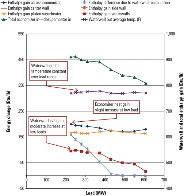 |
| 1. Pre-SCR boiler heat balance. Before installation of the selective catalytic reduction (SCR) system, heat absorption in the economizer was fairly constant throughout the load range. Courtesy: GenOn Energy |
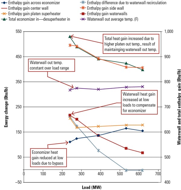 |
| 2. Post-SCR boiler heat balance. After installation of the SCR system, the economizer heat absorption fell off significantly at reduced loads. Courtesy: GenOn Energy |
Pre-SCR installation, heat absorption in the economizer was fairly constant throughout the load range. Post-SCR, economizer heat absorption fell off significantly at reduced loads. The waterwall outlet temperature setpoint was steady across the load range, so the waterwall outlet temperature is held steady in both cases by the firing rate control. The heat absorption in the waterwall circuit changes in the opposite direction from the economizer heat absorption pre-SCR installation and post-SCR installation. In fact, at the minimum load point, the heat absorption values for the economizer and waterwall circuits have effectively reversed. This means that the total heat absorption from the economizer inlet to the waterwall outlet has been maintained, but the contribution from the individual sections has changed considerably.
Finally, the total heat absorption at low load has increased. This is due to the added heat absorbed by the platen superheater as a result of increased firing rate to maintain waterwall outlet temperature. The waterwall circuit cannot absorb all of the additional heat input, so some is absorbed by the platen superheater. The waterwall outlet temperature was maintained, so this added heat is not needed in the platen superheater and leads to elevated temperatures. Notice the platen superheater gain at low load in Figure 2. The superheat sprays function to limit the effect on the final superheater inlet/outlet temperatures, but the platen superheater has no similar control element available.
Intermediate Boiler Temperatures Prior to MPC Upgrade
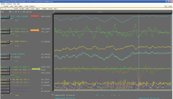
The boiler supercritical water/steam temperature profile provides insight into the challenges of maintaining intermediate temperatures within acceptable limits during both steady and dispatch operation. Figure 3 represents the Unit 2 temperature profile prior to incorporating model-based control upgrades.
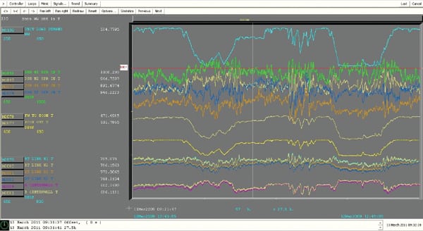 |
| 3. Temperature challenges prior to MPC upgrade. This chart represents the Unit 2 water/steam temperature profile prior to incorporating model predictive control–based control upgrades. The combination of higher firing rate (to offset the lower economizer heating) and the north/south temperature maldistribution results in excessive desuperheater inlet steam temperatures on the north side, particularly at low loads. Courtesy: GenOn Energy |
Figure 3 presents the unit load, the four desuperheater inlet steam temperatures (North 1/2 and South 1/2), the economizer inlet and outlet water temperatures, the six waterwall steam temperatures (including the four outlet temperatures: BT Link North 1/2 and South 1/2), and the two center wall intermediate steam temperatures.
The trends depicted in Figure 3 illustrate several issues. First, as load decreases, the economizer outlet temperature drops at a steeper rate than the economizer inlet temperature. This is a change from the original design and is caused by the gas bypass around the economizer to satisfy SCR minimum gas inlet temperature requirements. Because the final steam temperature setpoint at low load remains at the pre-SCR value, the intermediate boiler sections must absorb more heat, as illustrated by the higher center wall steam temperatures and desuperheater inlet steam temperatures at low load.
The second issue is the north/south temperature maldistribution. It begins with a split between the north and south waterwall outlet temperatures (BT links) and amplifies to the north and south desupheater inlet temperatures. The split exists at all loads but is greater at lower loads.
For example, the 17F split between north/south waterwalls jumps to a 67F split between north/south desuperheater inlet temperatures. The combination of higher firing rate (to offset the lower economizer heating) and the north/south temperature maldistribution results in excessive desuperheater inlet steam temperatures on the north side, particularly at low loads.
Intermediate Boiler Temperatures Following MPC Upgrade
Following the expansion of the MPC system to include north/south steam temperature distribution, the boiler supercritical north/south steam temperature profile became more balanced, as shown in Figure 4, particularly at intermediate and higher loads. However, at lower loads the allowable range of air distribution and other variables was restricted, compromising the ability to impact north/south temperatures.
 |
| 4. Striking a better balance after MPC upgrade. This chart represents the Unit 2 water/steam temperature profile after incorporating model predictive control–based control upgrades. The boiler supercritical north/south steam temperature profile became more balanced, particularly at intermediate and higher loads. The benefit is fewer incidences of high desuperheater inlet temperature and a lower average temperature, promoting longer tube life. Courtesy: GenOn Energy |
The north/south split is nearly eliminated at intermediate and high loads but exists at lower loads. The mean north/south waterwall split decreased to a 7F split, and the desuperheater split was lowered to 31F, with nearly balanced conditions at intermediate and high loads. The benefit is fewer incidences of high desuperheater inlet temperature and a lower average temperature, promoting longer tube life.
Using Control Technology to Enhance Plant Performance
The value of control technology is significant when it provides continuous improvement in approaching the theoretical best that the mechanical limitations allow. It ensures improved economics in utilizing what is currently available and helps meet performance and component protection goals, while corrective mechanical changes can proceed as economics and circumstances allow.
In this case, significant value was gained at the Morgantown plant by the major improvement in balancing the desuperheater temperatures for waterwall control on both units at intermediate and high loads. This, along with the other enhancements, resulted in higher ramp rates over an expanded generation range.
The authors wish to acknowledge the assistance of the following people in the drafting of this article: Tom Turk, Morgantown Generating Station plant manager; Jurgen Brat, Morgantown Generating Station engineering manager; and John Gay with PowerMax Consulting.
— Donald Andrasik (don.andrasik@genon.com) is a senior DCS engineer for GenOn Energy, assigned to Morgantown Generating Station. John McNulty (john.mcnulty@genon.com) is a senior DCS engineer for GenOn Energy at Morgantown Generating Station. Don Labbe (donald.labbe@invensys.com) is a consulting control engineer for Invensys Operations Management, based in Foxboro, Mass. He is an ISA fellow and director for ISA POWID.