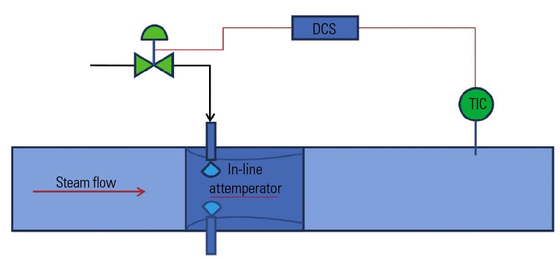
Desuperheaters—often called attemperators—in heat-recovery steam generators (HRSGs) are located between the primary and secondary superheaters and reheaters, and sometimes after the final stage of superheating (Figure 1). They are responsible for controlling steam temperature in accordance with start-up and steam-turbine-inlet requirements. The attemperators also prevent thermal damage to superheater and reheater tubes, and to outlet steam piping and downstream equipment.
1. Where you’ll find them. Attemperators for heat-recovery steam generators (HRSGs) are located between the primary and secondary superheaters and reheaters, and sometimes after the final stage of superheating. Courtesy: CCI International Ltd.
Interstage attemperators for superheaters typically see pressures up to 1,900 psig, temperatures to 1,020F, and steam flow rates to 660,000 lb/hr. Reheater attemperators experience similar temperatures and flow rates, but pressures normally go to only 450 psig.
Problems with attemperators
The addition of unwanted water to the steam line due to improper operation of an attemperator, or to the inability of its control element to remain leak-tight, is a major concern of operators. Failure of the attemperator to control the injection of water into interstage lines often produces thermal-shock damage to hardware and piping. In severe cases, the unatomized water will even erode piping. In most cases, the usual consequences are a forced outage and an expensive repair bill.
Another problem seen with interstage attemperators, though not as catastrophic, is their inability to control final steam temperature within specified limits. This occurs when the attemperator lacks sufficient turndown, or if installation is poor, or when the leakage across the attemperator’s control element exceeds the demand for spray water. Such failures reduce the steam turbine’s efficiency and electrical output.
Root causes of these problems include poor design of the attemperator and/or spray-water control element, poor installation, and improper control instrumentation.
Design considerations
The service requirements for interstage desuperheating are extremely demanding. As the HRSG cycles, attemperator hardware can remain for extended periods at elevated temperatures without spray water flowing through it. Adding insult to injury, the hardware then is quenched instantaneously by relatively cool spray water.
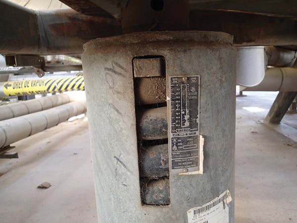
Attemperator designs with flow-control elements in the steam path—the multinozzle probe style shown in Figure 2, for example—are particularly susceptible to such damage. Cycling causes fatigue and thermal cracks in critical components, including the nozzle holder, individual nozzles, the lower body, and piston rings.
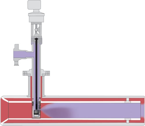
2. Vulnerable to damage. Multinozzle, probe-type attemperators generally are not recommended when the difference in temperature between the steam and spray water exceeds 450F. Courtesy: CCI International Ltd.
Multinozzle designs also are prone to internal flashing, which can occur when the flow of spraywater is extremely low and the water is allowed to heat up to saturation temperature before exiting the nozzles. Flashing fosters erosion of nozzles and the nozzle holder. Galling of piston rings and related components also is a possibility when temperature swings are large. This design also has the control element within the hot steam, making it subject to wide temperature variations.
Probe-style attemperators of any type are prone to vibration created by vortex shedding and the high-velocity head (kinetic energy) of the steam passing the probe assembly. The vibration induced by the vortices, in combination with the high temperature, can cause cracking of the weld joint between the probe’s mounting flange and its lower body. Thermal cycling can initiate cracking of the seal welds connecting the lower probe body with the nozzle head, thereby loosening the nozzle head and changing spray-angle orientation.
The turndown required for attemperation is quite high and often underestimated. Note that a 20:1 turndown in attemperation water flow does not necessarily equate to a 20:1 turndown in capacity for the flow-control element, or Cv. The spraywater control-element turndown requirement is influenced by variations in supply water pressure, steam pressure, and nozzle backpressure, which in combined-cycle power plants can be extreme. The last varies with flow demand.
In some cases, the difference between supply-water pressure and interstage steam pressure (Dp) at low flow is much higher than at high steam flow. In other cases, constant-speed boiler feedpumps provide spray water at relatively constant pressure, but interstage steam pressure slides during start-up—particularly when multiple HRSGs serve one steam turbine. For both situations, the variation in differential pressure across the operating range may require a spraywater flow-control element with extremely high turndown capability.
The turndown requirement of the spray-water flow-control element also is influenced by variations in pressure drop across the attemperator’s spray nozzles. This influence is much less pronounced in attemperators with spring-loaded nozzles than in those with fixed-area nozzles.
In addition to providing high turndown, the spray-water control element may experience high Dp at low flow and a low Dp at high flow and, therefore, must be able to handle these conditions.
Repeatable, tight shut-off of the control element is necessary. This calls for a high plug-to-seat thrust. Specify a trim exit velocity of less than 100 ft/sec to prevent cavitation and erosion damage. In short, users should look for a control valve that offers equal-percentage-characterized trim to maximize resolution during low Cv requirements, thereby ensuring tight control of spraywater and of outlet temperature.
Of course, proper installation is important to the success of every attemperator. Here are three cardinal rules to remember:
- Provide a straight run of pipe upstream of the attemperator of no less than three diameters. Installation of a liner in the inlet piping is recommended to ensure uniform geometry of the steam flow at the point of spraywater injection.
- Provide a straight run of pipe downstream of the attemperator. Insufficient distance between the attemperator and the first downstream elbow can cause the agglomeration of water droplets along the elbow wall, a phenomenon conducive to water fallout, thermal shock, inaccurate feedback from instrumentation to the flow-control element, and erosion.
- Install the temperature sensor downstream of the attemperator at a point where all the spraywater has been evaporated to avoid false readings and inaccurate feedback to the flow-control element.
Figure 3 indicates the recommended installation distances when attemperator spray—in conjunction with appropriate liner—is perpendicular to steam flow and nozzles are circumferentially mounted.
3. Measure carefully. The recommended installation distance is quite specific when the attemperator spray is perpendicular to steam flow.
Courtesy: CCI International Ltd.
Importance of proper atomization
Proper atomization and evaporation of the spraywater supplied by an attemperation system is necessary both for good temperature control and to prevent water carryover. The complete integration of injected water into superheated steam involves three steps: primary atomization, secondary atomization, and evaporation.
Primary atomization is the breakdown of water into droplets by the attemperator’s nozzles. The goal is to create as small a droplet as possible, regardless of the water spray flow rate. Variable-area nozzles offer this capability. They can provide good primary atomization at flows down to less than 220 lb/hr, and they are self-cleaning.
Fixed-orifice nozzles, by contrast, are sized for the maximum flow rate and do a progressively poorer job of atomization as water flow decreases. The reason is the inherent reduction in Dp characteristic of reduced flows through fixed-area nozzles. They typically are limited to a 3:1 turndown.
Secondary atomization refers to the breakup of large droplets by the dynamic force of the steam flow. However, for secondary atomization to occur, the dynamic forces acting on a droplet must be greater than the viscous forces holding the droplet together. This is a function of the Weber number (We), which is equal to the dynamic force divided by surface tension. The equation is:
Surface tension (stabilizing) force s
where D is the droplet diameter, U the density of steam, r the characteristic velocity, and s the surface tension (which depends on water temperature). At Weber numbers greater than 12, the aerodynamic or destabilizing force will overcome surface tension—the stabilizing force—and the droplet will break up.
To achieve good secondary atomization, design engineers suggest injecting the water spray perpendicular to the steam flow (Figure 4) rather than parallel to it, as in Figure 2. In HRSG main and reheat attemperator applications, steam velocity is sufficiently high to maximize relative velocity and ensure efficient secondary atomization under all operating conditions.
4. The right angle. Injection of spray water perpendicular to steam flow improves atomization and offers other benefits as well.
Courtesy: CCI International Ltd.
The small droplets produced by secondary atomization boil and evaporate. The time needed to complete the evaporative process depends on the total surface area of the water volume and is proportional to the square of the droplet diameter. Any droplets that do not evaporate before reaching the temperature sensor may wet the sensor and make it difficult to control steam temperature as intended.
Inadequate design of the attemperation system can result in a combination of poor control and poor atomization during transients that would permit carryover of water into the secondary superheater, damaging headers and tubes.
Design considerations
Attemperators for HRSG service operate during cold, warm, and hot restarts, as well as during load transients. During steady-state operation, however, desuperheating should not be necessary. This means that the attemperator assembly is exposed for extended periods to rated steam temperature without cooling by injection water.
When injection water is required, attemperators are quenched instantaneously from operating steam temperature to the temperature of the spraywater—a difference of 630F to 810F at most plants. Attention must be paid to thermal shock at the design stage, because attemperating systems for HRSGs will experience many quenching cycles in their lifetimes, particularly in cycling power plants.
Attemperators with integral control valves, such as the multinozzle unit shown in Figure 2, should be analyzed carefully before writing your specification. Here’s why:
- Because the nozzle head is downstream of the water control/isolation point, it can be at steam temperature when cool water is admitted.
- Thermal fatigue has been experienced at some plants that have been cycled fewer than 500 times.
- The flow-control element is prone to cracking, sticking, and leaking.
In addition to being vulnerable to thermal shock, probe-style attemperators are susceptible to bending moments created by the flow of steam and to flow-induced vibration as well. If the vibration frequency matches the natural frequency of the probe, there is risk of catastrophic damage. Multinozzle heads are even more susceptible to the effects of thermal shock than simple, fixed-nozzle probe arrangements because of their greater mass.
You can avoid thermal fatigue issues by specifying a desuperheating system that has a separate spray water flow-control element located outside the hot steam environment. Extensive analysis and testing indicate that attemperators with integral control-valve elements should not be specified when the difference between the temperatures of the steam and spray water is greater than 450F.
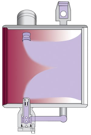
Another recommendation: Specify a thermal barrier to separate the hot and cold working elements. It will mitigate the intensity of the thermal cycles experienced by critical components (Figure 5).
5. Provide protection. A thermal barrier mitigates the intensity of thermal cycles experienced by critical components. The liner protects steam piping from thermal shock and helps improve secondary atomization. Courtesy: CCI International Ltd.
There’s more to designing a liner than just providing more metal to protect steam piping against thermal shock. A properly engineered liner is also capable of:
- Increasing steam velocity to improve secondary atomization.
- Creating vortices that improve atomization and enhance mixing.
- Assisting with heat transfer and evaporation.
- Controlling the penetration of the spray pattern by flow profiling.