While several methods exist for sizing collector pipes on steam lines, the results obtained from the various approaches can be quite different. This article will show how design parameters can be used to calculate the dimensions much more accurately.
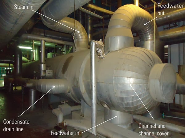
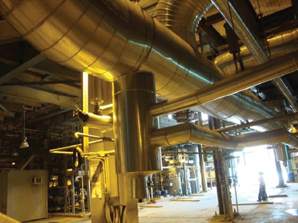
In the steam lines of thermal and nuclear power plants, condensed steam is usually discharged from components such as steam traps, control valves, or restriction orifices through draining lines that join to a collector pipe that connects to the condenser.
The size of this collector is typically calculated by applying rules of thumb that can vary significantly depending on the reference used. One source may suggest using a cross section equal to the sum of the sections of the connecting lines, another source may suggest several times this sum, while yet another suggests limiting the fluid velocity to small values, such as 50 ft/sec or less.
The result is that there are very different designs. For example, a 10-inch-diameter collector may have two lines of 4 in. plus two lines of 6 in. connected to them, while another collector of 16-in.-diameter only has two 2-in. lines connected.
In order to optimize the design of these collectors, the following guide takes into account the capacity of each draining line, the pressure in the connecting point, and the equivalent length of the collector.
System Parameters Are Key
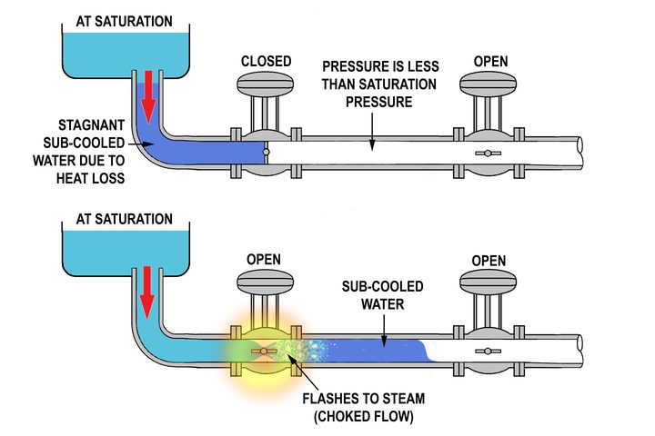
The condensate collected in the drip pots of the steam lines is saturated or sub-cooled water that flashes when passing through the component, which continues flashing along the drain line. If the pressure of the condensate at the component entrance is the saturation pressure (PS) and the resistance coefficient of the component plus the line is K, the critical pressure at the collector connection (PCR) may be calculated using the graphs in Figures 1 or 2.
The maximum draining capacity of the line is calculated applying the following equation for saturated water:
W / d2 = 280 CE [(PS – PCR) / (ve K)]0.5 ln PS
where:
W is the flow rate of each drain line (lb/hr),
d is the internal drain piping diameter of the selected line with the minimum PCR value (in.),
CE is the expansion coefficient of the saturated water,
PS is the saturation pressure at the entrance of the component (psia),
PCR is the critical pressure at the end of the pipes (psia),
ve is the specific volume to PS (ft3/lb), and
K is the resistance coefficient of the pipe.
This equation has been deduced by the author from a 1961 research paper titled “Adiabatic Flow of Flashing Liquids in Pipes” written by M. Sajben and published by the American Society of Mechanical Engineers in its Journal of Fluids Engineering.
The CE is obtained from Figure 3 for the intersection of K with the critical conditions line. Figure 3 is based on PS = 1,000 psia as a reference pressure and the equation allows using the CE value for whichever other pressure. The pressure drop (PS – PCR) is divided between the component and the downstream piping.
Design of the Collector
When each line that connects to the collector is defined, knowing its flow capacity (W), the connection pressure (PCR), the saturation pressure at the component entrance (PS), and the resistance coefficient (K), the collector may be designated following these steps.
First. Select the connecting line with the minimum value of PCR and calculate the total flow (WT) that must be drained for the collector to the condenser as the sum of the flows of all connecting lines. If there are two or more connecting lines that have the same minimum value of PCR, select the line that has the greatest flow. For the structural design of the collector, use the maximum value of PCR.
Second. Calculate an equivalent diameter of the selected line (Do) as:
Do = d (WT / W)0.5
This equivalent line will have the same resistance coefficient (K) as the selected line, and it should be designated Ko.
Third. Calculate the resistance coefficient of the collector (KC) with the following expression:
KC = 1 + f [(LC / D) + (60 x n)]
where:
f is the pipe friction factor,
LC is the straight length of the collector (in.),
D is the internal diameter of the pipe collector (in.), and
is the number of the connecting pipes to the collector.
The friction factor inside the collector (f) will correspond to turbulent flow, so it may be expressed by the equation:
f = 0.022 / D0.207
Note that the value of the resistance coefficient for the end of the collector is 1, and the equivalent length (L) divided by the equivalent drain pipe diameter (D) of each connection to the collector is 60, assuming them as standard tees with the flow through the branch.
Select a value for D greater than or equal to Do. Calculate KC using the equation shown earlier, and KL using the following equation:
KL = Ko (D / Do)4, and
K = KC + KL.
In Figure 1 or 2, obtain the value of PCR for K and PS. This PS is the saturation pressure of the selected line at the entrance of the component, and PCR is the critical pressure at the end of the collector.
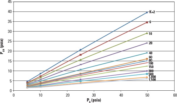 |
| 1. Low-pressure scenario. Relationship of saturation pressure (PS), critical pressure (PCR), and resistance coefficient (K) for saturated water flow through pipes. Source: E. Casado |
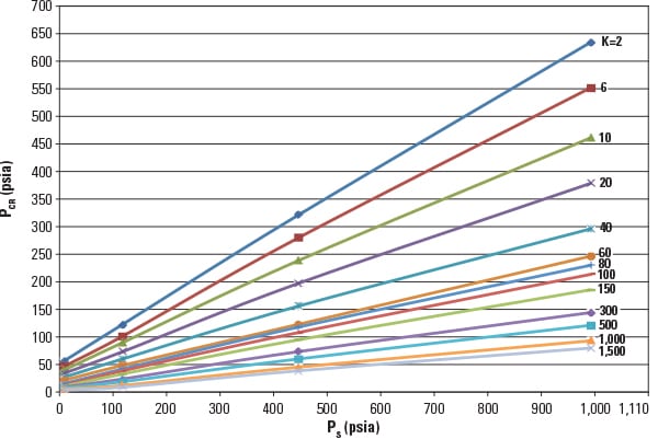 |
| 2. Higher-pressure scenario. Relationship of saturation pressure (PS), critical pressure (PCR), and resistance coefficient (K) for saturated water flow through pipes. Source: E. Casado |
Fourth. Apply the equation (shown previously) to calculate the maximum draining capacity of the line. The calculated value of W / D2 must be equal to (or greater than) WT / D2; otherwise, select a greater value of D and repeat steps 3 and 4.
Note that CE is calculated in Figure 3 for the intersection of K with the critical conditions line.
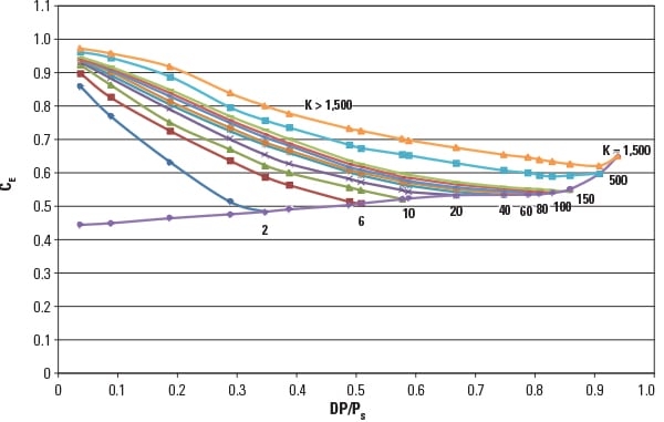 |
| 3. Critical conditions. Expansion coefficient (CE) for saturated water flow through pipes at saturation pressure (PS) = 1,000 psia. Source: E. Casado |
Fifth. Finally, check the velocity of the fluid at the end of the collector and select the appropriate material for the application.
There is no specific limit for the recommended maximum velocity. In at least one reference, the maximum velocity values for different investigated steels are 85 to 390 ft/sec. Values of 75 ft/sec for continuous service and 100 ft/sec for intermittent service could be valid for carbon steel collectors. For higher velocity values, select alloy steel or stainless steel.
To calculate the velocity of the flashing water at the end of the collector, first it is necessary to determine the percentage of the steam of each draining stream in the expansion from its PS to PCR at the end of the collector. This may be done using Figure 4.
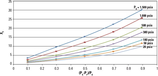 |
| 4. Flashdance. Percentage of steam (xF) in the expansion of the saturated water from saturation pressure (PS) to final pressure (PF). Source: E. Casado |
With the steam tables, we can calculate the specific volume (ve) of each draining stream, ve1, ve2, and ve3, and estimate the weighted average specific volume (veT) by:
veT = ( ve1 W1 + ve2 W2 + ve3 W3) / WT
The velocity (V) may be calculated by the equation:
V = 0.051 veT WT / D2
Putting Theory into Practice
The following numerical example shows how to design a pipe to collect the drains from the three lines with steam traps shown in Figure 5.
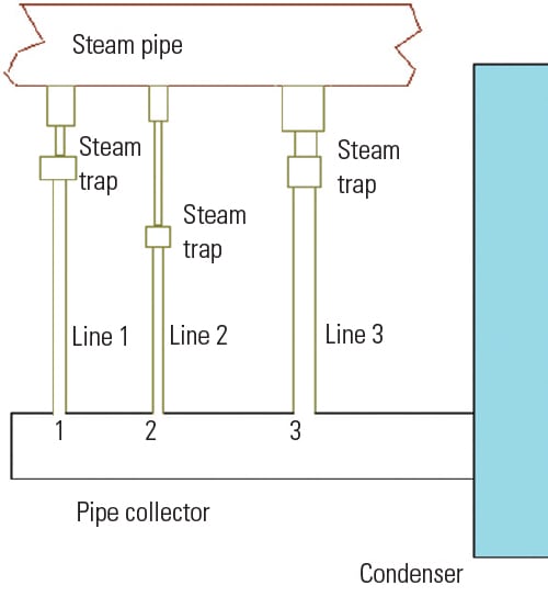 |
| 5. A typical scenario. The steam pipe shown has three drain lines with steam traps to divert moisture from the line to the condenser. Source: E. Casado |
Line 1: PS1 = 100 psia, PCR1 = 40 psia, K1 = 30, d1 = 2 in., and W1 = 29,570 lb/hr.
Line 2: PS2 = 50 psia, PCR2 = 19 psia, K2 = 40, d2 = 1.5 in., and W2 = 8,900 lb/hr.
Line 3: PS3 = 40 psia, PCR3 = 25 psia, K3 = 9, d3 = 3 in., and W3 = 47,650 lb/hr.
The collector pipe has a straight length, LC = 394 in.
Calculate collector requirements, as follows:
■ Select line 2, because it has the minimum PCR value: 19 psia.
■ WT = 29,570 + 8,900 + 47,650 = 86,120 lb/hr.
■ Do = 1.5 (86,120 / 8,900)0.5 = 4.67 in.
■ Ko = K2 = 40.
As the maximum PCR value is PCR1 = 40 psia, a schedule 40 pipe will be enough to resist the internal pressure. A 5-in. schedule 40 pipe may be selected, because its internal diameter (5.047 in.) is greater than Do = 4.67 in. The next step is to calculate the resistance coefficient:
■ KC = 1 + (0.022 / 5.0470.207)[(394 / 5.047) + (60 x 3)] = 5.
■ KL = 40 (5.047 / 4.67)4 = 54.6. Therefore, use KL = 55.
■ K = 5 + 55 = 60.
■ In Figure 1, for PS = 50 psia and K = 60, PCR = 16 psia.
■ In Figure 3, for K = 60, CE = 0.54.
Next, the total flow rate is calculated as follows:
■ WT / D2 = 86,120 / 5.0472 = 3,381 lb/hr-in2.
■ W / d2 = 280 x 0.54 [(50 – 16) / (0.01727 x 60)]0.5 ln 50 = 3,388 lb/hr-in2 > 3,381.
Therefore, the collector diameter of 5-in. schedule 40 pipe has enough capacity to discharge the total flow.
Now, we must check the velocity of the fluid at the end of the collector:
■ W1 expands from 100 psia to 16 psia. Using Figure 4, (100 – 16) / 100 = 0.84, therefore the steam content of this stream is 11.8%. Likewise, W2 = 6.6% and W3 = 5.1%.
■ With the aid of the steam tables, we obtain: ve1 = 2.93 ft3/lb, ve2 = 1.65 ft3/lb, and ve3 = 1.25 ft3/lb.
■ veT = [(2.93 x 29,570) + (1.65 x 8,900) + (1.25 x 47,650)] / 86,120 = 1.87 ft3/lb.
■ V = 0.051 x 1.87 x 86,120 / 5.0472 = 332 ft/sec.
Considering that this is such a high value, selecting a collector of 8-in. schedule 40 pipe may be more appropriate. In this case, D = 7.981 in., resulting in a velocity of V = 322 x (5.047 / 7.981)2 = 129 ft/sec. Therefore, a collector of this size made from alloy steel may be appropriate. For the sake of comparison, had the sum of the sections been used to size the collector, as suggested by another reference, the result would have been an undersized collector with a 3.91-in. diameter, while following the directions provided by another resource would have resulted in an oversized collector with a diameter of 12 inches. ■
— Emilio Casado (ecf@empre.es) is a consulting engineer with Empresarios Agrupados. He has experience working as a mechanical project chief involved in the design, construction, and startup of nuclear and thermal power plants.